Set the outage objective and limits
Start by stating what the outage must accomplish: inspect existing gear, replace an assembly, connect a new section, or complete another defined change. Record the affected lineup, work area, target outage window and conditions that permit work to start. Confirm who can authorize the shutdown, who controls switching, and who can approve a schedule change.
Use current one-lines, equipment schedules, operating procedures and field observations to establish the actual boundaries. Drawings may not reflect later modifications, alternate feeds or temporary connections. Have qualified electrical personnel verify the configuration and determine the required isolation and verification process. Resolve discrepancies before procurement and outage planning rely on them.
Map loads and continuity needs
List loads served by the affected equipment and identify which can be interrupted, which need temporary support, and which must remain in service. Coordinate with operations on process dependencies, restart sequences, critical alarms, life-safety systems and controls that could be affected indirectly. A load that appears separate on a schedule may share a control power source or upstream device.
Ask engineering to evaluate available transfer paths, temporary power options and their limits for the actual system. Confirm source capacity, connection points, protective-device coordination and grounding requirements before selecting a continuity plan. Do not treat a temporary feed or alternate path as available until its suitability and operating method have been reviewed and approved.
Define isolation and work boundaries
The shutdown plan should identify the equipment to be de-energized, possible sources of energy, boundaries for adjacent energized equipment and the sequence for isolation and verification. Include backfeed possibilities, control circuits, stored energy and any generator, photovoltaic, battery or alternate utility source that could affect the work. Site procedures and applicable safety requirements govern the final switching and lockout steps.
Assign clear authority for switching, lockout/tagout, absence-of-voltage verification, work release and restoration. Coordinate the plan with the facility’s qualified electrical personnel and contractor before the outage. If the replacement scope changes the lineup or connections, engineering review must address the revised conditions; procurement documents alone do not establish a safe work boundary.
Specify replacement gear for the outage
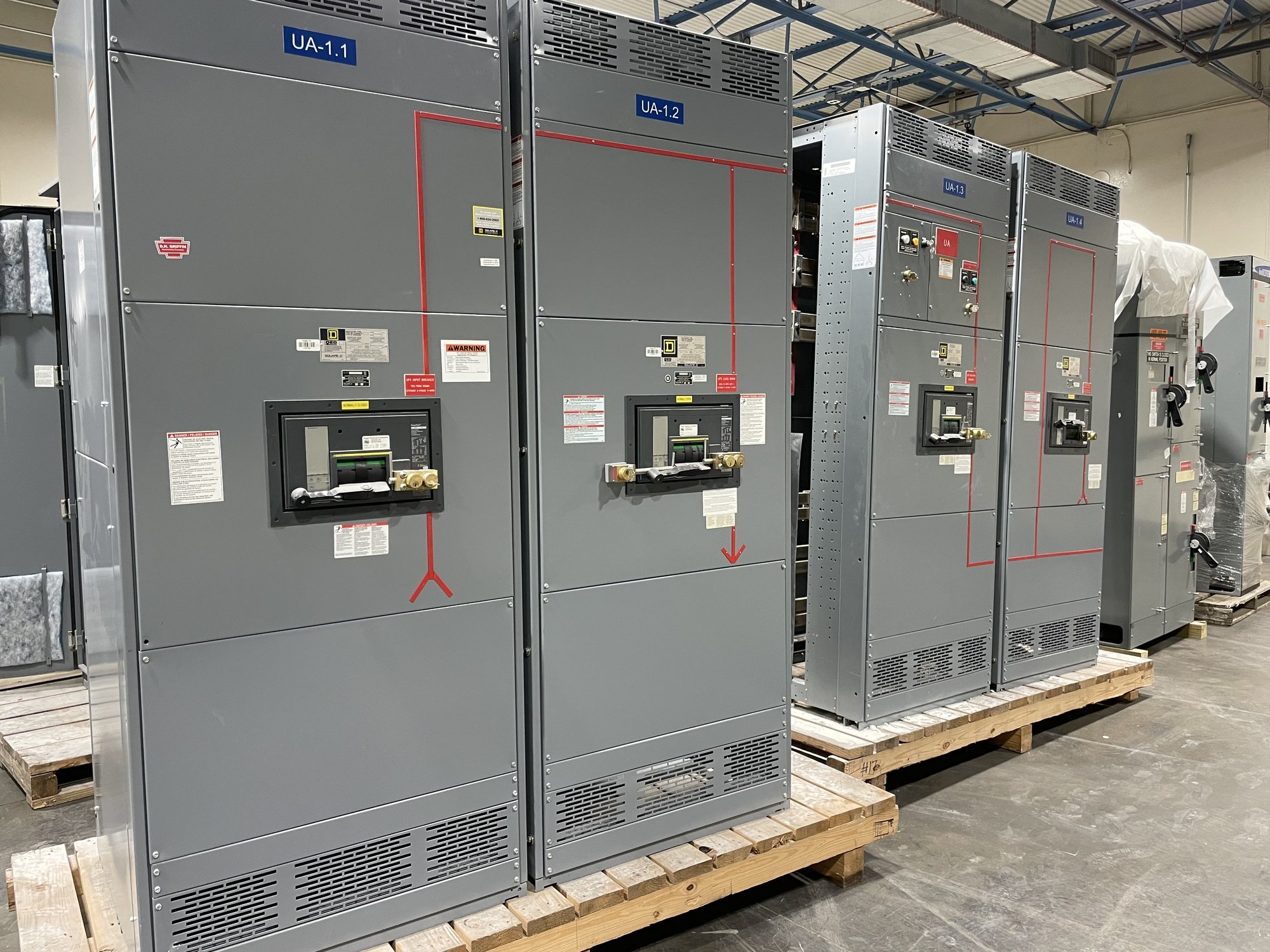
For a new switchboard assembly, provide the existing system information needed to develop a compatible configuration: system voltage and phase, available fault-current data, bus and feeder requirements, source arrangement, enclosure conditions, dimensions, cable or bus connections, and control or metering needs. Identify what will be reused, removed or modified. UL 891 applies to switchboard assemblies; it is not a blanket listing for medium- or high-voltage switchgear.
Engineering and procurement should settle interface details early, including access and lifting constraints, termination space, entry direction, instrument-transformer or control requirements, and any site-specific sequencing. Confirm the requested ratings and configuration against the project’s engineering and authority review. The manufacturer can build to an agreed scope, but exact design, availability and production timing must be confirmed for each order.
Prepare people, materials and contingencies
Name the outage lead and define handoffs among facility operations, electrical engineering, the installing contractor, equipment supplier and any other affected parties. Share the approved schedule, switching responsibilities, site access rules, material staging plan, communication method and criteria for stopping work. Verify that the people performing electrical tasks are qualified and authorized for their assigned duties.
Build contingencies around realistic failure points: a load that will not transfer, a drawing discrepancy, damaged conductors, unexpected site conditions, a delayed shipment or a test result that prevents restoration. Decide who can extend the outage, what loads receive priority, and what condition triggers a return to the prior state or another approved plan. Do not improvise energized work or bypass required review to meet a schedule.
Coordinate delivery and restoration
For a Georgia project, align the equipment delivery window with the site’s receiving hours, unloading capability, access route, staging area and outage milestone. Nationwide shipping supports projects across Georgia, but the delivery date, configuration and handling plan must be confirmed for the specific order. Share site constraints and the required-on-site date when requesting a quote so they can be considered alongside the technical scope.
For a useful quote request, provide the one-line diagram, equipment schedules, ratings and dimensions, connection details, required options, delivery location, target outage window and known access or unloading limits. After installation, define inspection, testing, documentation, approval and restoration responsibilities before work starts. Close the plan by confirming who accepts the completed equipment, authorizes re-energization and communicates that affected loads may return to service.