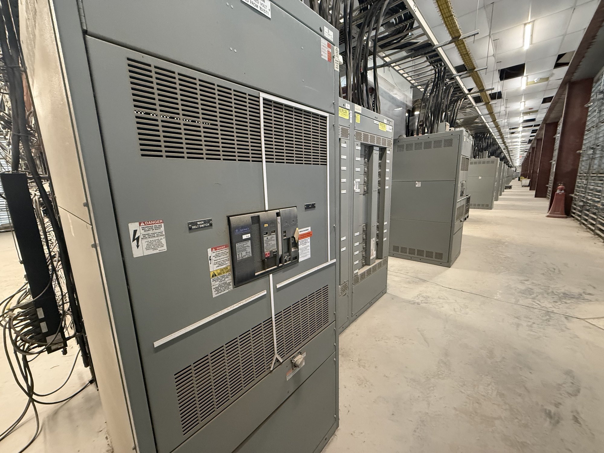
What time-current coordination evaluates
A time-current curve plots how long a protective device takes to operate at different levels of current. An engineer compares curves for devices connected in series, such as a downstream breaker and an upstream breaker, to assess whether the downstream device is expected to clear a fault first. The review considers each device’s operating range, not a single trip point.
Coordination is a design objective, not a guarantee that every fault will isolate only one circuit. Device curves can overlap, and high fault current may cause instantaneous or short-time elements to operate in ways that limit selectivity. The engineer evaluates the system’s fault levels, device characteristics and operating modes, then documents where coordination is achieved and where constraints remain.
System information the engineer needs
The study needs a current one-line diagram showing sources, transformers, bus sections, ties, feeders, loads and protective devices. Provide utility data at the service point, transformer impedance and connection details, conductor sizes and lengths, and available motor or generator contributions. Identify normal and alternate configurations, including tie-breaker positions and any planned changes that affect fault current.
For existing devices, share manufacturer, model, frame or sensor rating, trip-unit type, installed settings and available curve data. For proposed switchgear, identify the intended lineup arrangement, incoming and feeder functions, interrupting requirements established by the project engineer, and the devices that must coordinate with equipment upstream and downstream. Flag missing records early; assumptions should be visible and reviewed rather than mistaken for verified field data.
Settings depend on more than curve spacing
Engineers review long-time, short-time, instantaneous and ground-fault functions where applicable, along with fuse characteristics and relay time-current behavior. They compare device curves against conductor and transformer damage limits and consider load current, motor starting, transformer inrush and other expected events that could cause unwanted operation. The study may examine whether proposed settings are practical for the actual operating conditions.
A wider time gap between devices can support selectivity, but it can also increase the time equipment experiences a fault. Some breakers offer adjustable functions; others have fixed characteristics or limited setting ranges. The engineer must balance coordination goals with equipment protection, available device options and the project’s governing design criteria. Settings should not be selected from a generic table without system-specific analysis.
Operating modes and project constraints
A system may have different fault currents when utility supply, on-site generation or alternate feeds are in service. A setting that coordinates in one configuration may not coordinate in another, so the study scope should identify credible operating modes and the devices that change state. For complex systems, the engineer may need separate curve sets or a documented basis for the selected settings.
Procurement decisions can affect the study outcome. Available trip-unit functions, sensor choices, breaker frame sizes and switchboard section arrangements may constrain the range of possible settings. UL 891 applies to switchboards; it is not a blanket listing for medium- or high-voltage switchgear. The project engineer must define applicable equipment standards, ratings and approval requirements for the actual system.
Turning study results into a buildable specification
Study deliverables commonly identify evaluated devices, assumptions, time-current plots, recommended settings and coordination limitations. The project team should establish who will perform the study, which drawings and field data form its basis, and whether the scope includes revisions after equipment selection or installation. Confirm how settings will be recorded and handed to the qualified personnel responsible for implementation and verification.
When requesting a quote for new switchgear, share the latest one-line diagram, device schedule, study status, desired lineup functions and any known setting or coordination requirements. Ask whether proposed devices and configurations can support the engineer’s intended functions, and identify information still pending. For Georgia projects, provide the delivery location and required site sequence so equipment scope and shipping can be coordinated with the project schedule; availability and timing are confirmed for each order.
Close the engineering and procurement loop
Before releasing a design for manufacture, align the study assumptions with the selected equipment and the project’s final system configuration. Changes to transformer data, conductor routing, source contributions or breaker selections can affect curves and settings. Route revised information to the study engineer and resolve discrepancies between the study, drawings and equipment schedule before treating settings as final.
Start with the one-line diagram and a list of known devices, sources and operating modes. Note which data are verified, which are estimated and what remains undecided, then ask the engineer to define the study boundary and required deliverables. That clear handoff gives the switchgear specification a traceable basis and helps procurement evaluate a configuration against the actual coordination objective.