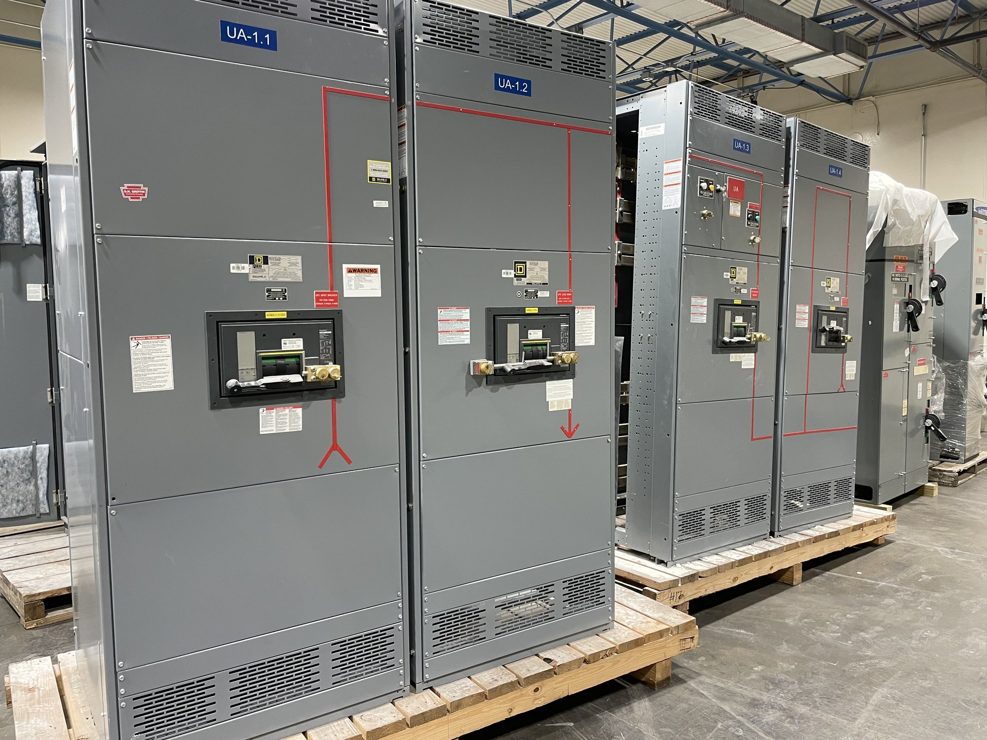
Define what must be verified
A useful verification plan starts with the purpose of each meter: operating display, energy accounting, demand tracking, alarms, or data sent to a supervisory system. Those uses can require different levels of checking. Identify each meter and measurement point, the values needed, and the party that will use the results. A one-line diagram, meter schedule, control schematic, and communications architecture help establish the intended arrangement.
Clarify whether the scope covers factory checks on a new switchboard, field verification after installation, or both. Factory work can confirm the configured assembly and available test points; field work can also reveal errors introduced by external wiring, network setup, or installation. State which devices and circuits are included, what documentation is expected, and whether the work must coordinate with commissioning or an outage.
Check wiring and phase relationships
Meter accuracy depends on more than the meter itself. Verification may trace voltage inputs and current-transformer secondary circuits to the correct meter terminals, confirm phase association and polarity, and inspect specified fusing or shorting provisions. For three-phase systems, an incorrect phase pairing or reversed polarity can produce plausible but misleading power and energy values. The approved drawings and meter instructions should govern test methods and circuit handling.
Before quoting, provide the switchboard drawings, meter make and model, circuit count, and any known wiring changes. Explain whether voltage and current circuits originate inside the assembly or arrive from external equipment. Testing current-transformer circuits requires qualified personnel and procedures appropriate to the installation; never open an energized CT secondary. The work plan should identify isolation needs and who is responsible for safe access.
Confirm transformer ratios and scaling
Where instrument transformers supply the meter, compare configured ratios and scaling with the approved transformer data and design documents. Record primary and secondary ratings, meter settings, and any multiplier used for displayed or accumulated values. A mismatch can make readings consistently high or low even when the wiring is correct. If the design uses direct voltage inputs or different sensing arrangements, document those instead of assuming a conventional CT/PT configuration.
Ratio verification has limits: checking a programmed value against a drawing does not independently prove an instrument transformer’s field performance. State whether the request is for configuration review, circuit verification, or testing that requires separate equipment and access. If transformer data, wiring records, or the approved settings are missing, resolve the discrepancy with the responsible engineer before treating a reading as a valid baseline.
Review communications and displayed data
For networked meters, verify the intended protocol, address, baud rate or network settings as applicable, and the mapping of required values to the receiving system. Compare locally displayed values with values received remotely, including units, sign conventions, scaling, and timestamps where relevant. A communications link can be active while individual register assignments or scaling remain incorrect, so test the specific points used by the facility rather than relying on a general connectivity indication.
Share the system interface details, point list, gateway information, and the party responsible for controls integration. Confirm whether verification ends at the meter, at a switchboard gateway, or at the facility system. Network access, cybersecurity rules, proprietary software, and unavailable upstream equipment can limit testing. Record excluded points and dependencies clearly so the handoff distinguishes a verified value from one that could not be observed.
Compare readings with a reference
A comparison against a suitable reference can help assess whether indicated voltage, current, power, or energy is reasonable under defined conditions. The test record should identify the reference instrument or method, the measurement point, operating load, system conditions, and observed difference. Results are meaningful only when the reference is appropriate for the quantity and range being checked and the comparison uses compatible units and timing.
Do not treat a brief comparison as proof of accuracy across all loads or operating states. Load variation, harmonics, phase imbalance, instrument-transformer characteristics, and measurement location can affect results. If no stable operating condition exists, document that limitation and agree whether testing should be repeated during a suitable operating window. Acceptance criteria must come from the project specification or responsible engineering authority, not an assumed universal tolerance.
Plan the order and closeout
For a new, custom-built switchboard, send the meter schedule, approved drawings, required point list, transformer ratios, communications requirements, acceptance criteria, and requested report format with the quote inquiry. Include the Georgia delivery location, site access constraints, installation and commissioning dates, and whether field verification is requested. These details help confirm the applicable scope, configuration, availability, and project timeline; exact arrangements are established for each order.
Closeout should identify each meter and circuit tested, settings reviewed, readings or communications points observed, reference method where used, exceptions, and unresolved dependencies. Ask who will receive the records and who approves any corrective changes. For a Georgia project, coordinate delivery timing with the site’s receiving and installation plan, while allowing the project team to schedule qualified field personnel and any required outage. Use the documented results to resolve discrepancies before relying on meter data for operations or reporting.