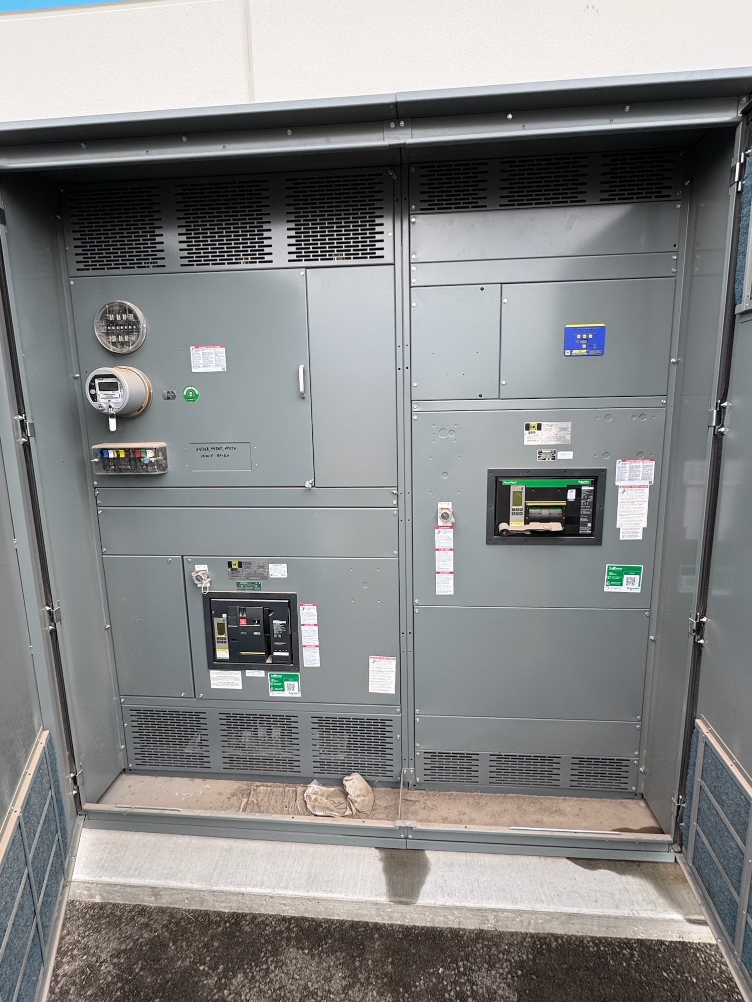
What a point-to-point check verifies
A point-to-point check confirms that a conductor lands at the intended terminals and devices shown on the approved drawings. A technician compares wire markers, terminal numbers, device identifiers, and connection points against the schematic, then checks electrical continuity using an appropriate test method. The objective is to verify the documented path, not merely to establish that some path exists.
This distinction matters in control circuits for breakers, relays, meters, indication, alarms, and interlocks. A wire connected to the wrong contact may show continuity while failing the circuit’s intended function. Continuity results therefore need to be read alongside contact designations, normally open or normally closed states, terminal plans, and any applicable wiring diagrams.
Use the approved drawing set
Testing should use the current, approved control schematics and associated terminal or connection drawings for the equipment configuration. Confirm drawing numbers, revisions, and any approved field changes before tracing conductors. If the panel wiring reflects a later revision than the copy on hand, record the mismatch and resolve which document governs before treating a result as a pass or failure.
Schematics may show a functional circuit, while a separate connection diagram identifies physical terminal locations and wire destinations. Both can be needed to reconcile a device contact with its actual terminal numbers. Where drawings omit a detail, show conflicting references, or leave a connection unclear, do not infer the intended wiring from appearance alone; route the question to the responsible engineer.
Plan the test around the circuit
Before testing, establish the approved test procedure, equipment condition, circuit boundaries, and who is authorized to perform the work. Identify connected electronics, relays, meters, surge devices, or other components that could be affected by a test method. Isolate or disconnect components only as directed by the applicable procedure and engineering documents. Continuity checks are not a substitute for required isolation, functional testing, or commissioning.
A low-resistance continuity instrument may be suitable for a specified point-to-point check, but test voltage, instrument selection, lead compensation, and acceptance criteria depend on the circuit and project requirements. Never apply an insulation-resistance test or other higher-voltage test to connected control devices without explicit direction. Follow equipment instructions and site safety rules; qualified personnel must control testing and any energization.
Record results and discrepancies
A useful record ties each check to a drawing reference and identifies the source and destination terminals, wire marker, result, test date, and tester or responsible party as required by project documentation. A clear record lets another reviewer understand what was checked without repeating the trace. Include the drawing revision used so results remain meaningful after later document updates.
When a wire is open, lands at an unexpected point, or appears to bridge connections that should be separate, document the observed condition and affected references. Do not quietly correct a discrepancy or mark it complete based on an assumed intent. Record the disposition, approved drawing change, and any retest needed so the as-built package reflects the configuration actually supplied.
Define scope before ordering
For a new switchboard or control assembly, clarify whether the project requires factory point-to-point verification, customer or site testing, a particular record format, or a witness and hold point. These are distinct scope decisions. Share the applicable control schematics, terminal plans, revision status, device list, special circuit requirements, and acceptance documentation with the manufacturer so the requested work can be evaluated against the actual design.
Also identify the assembly type, control functions, project schedule, delivery destination in Georgia, and any coordination requirements that affect documentation or shipment. Exact configuration, test scope, availability, and timeline are confirmed for each order. For UL 891 switchboard assemblies, the standard applies to the switchboard assembly; it does not by itself establish that a particular continuity procedure or test record is required.
Carry verified wiring into handoff
At handoff, align the test record with the final approved drawings and any approved revisions. Confirm that open items have an assigned disposition and that the receiving team knows which circuits were checked, which tests remain, and what procedures govern subsequent functional testing. This avoids treating a continuity record as proof that every control function has been exercised under operating conditions.
For a Georgia project, send the manufacturer the current drawing package, required point-to-point scope, record format, delivery location, and schedule constraints when requesting a quote. Ask which checks and documents can be included for the proposed configuration, and resolve drawing questions before release. That specific scope gives engineering, procurement, and the field team a clearer basis for review and acceptance.