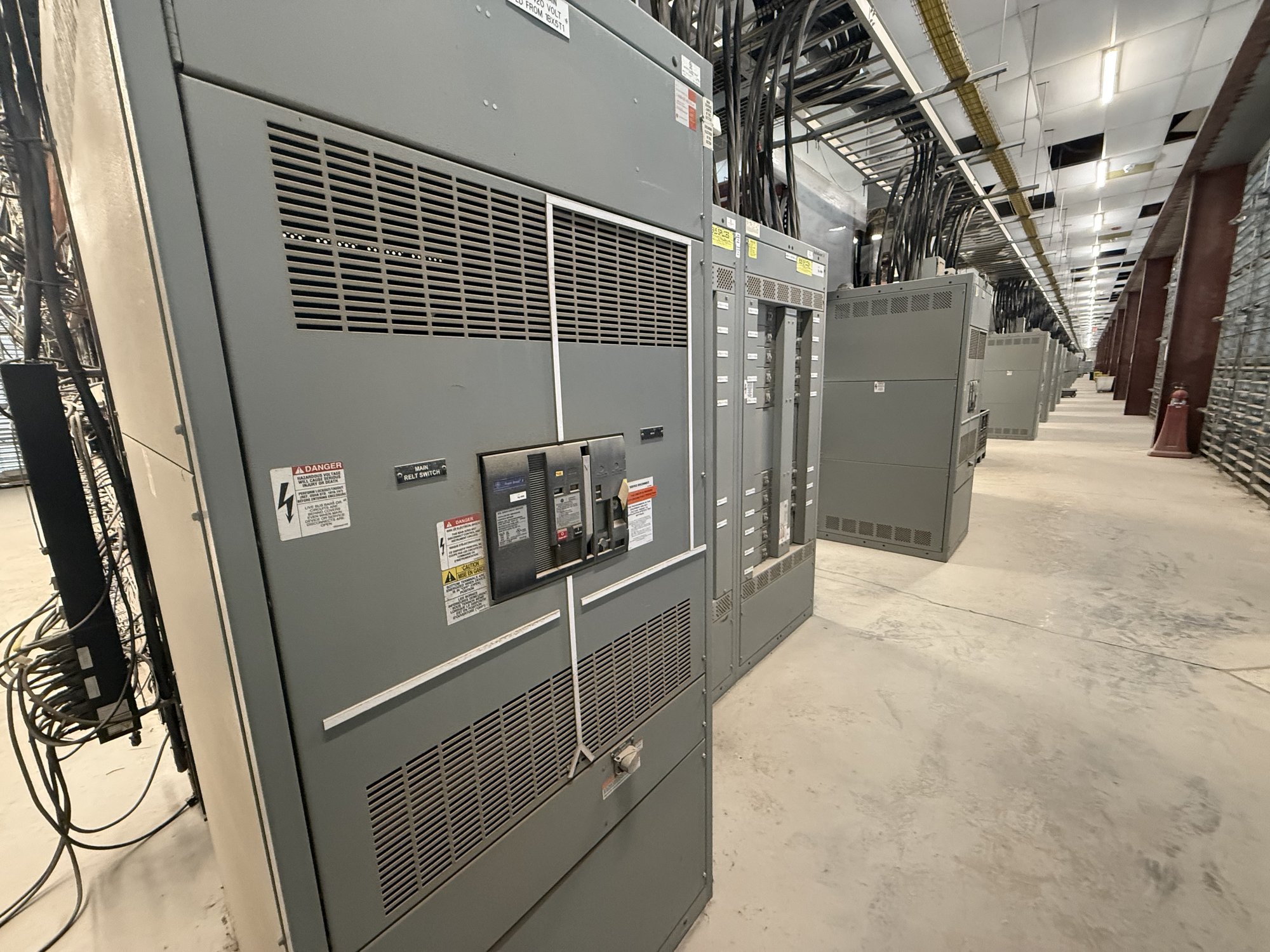
Set entry points from the equipment layout
Identify whether conductors enter from below, above, or through the side of the assembly, and show the intended entry zone on the electrical and equipment plans. Include conduit centerlines, sizes, quantities, and the direction each run approaches the gear. A general note such as “conduit in floor” does not establish usable space or confirm that the proposed route aligns with the equipment compartments.
Coordinate entry locations with the switchboard lineup, section boundaries, and access requirements. A conduit landing beneath one section may be impractical if the feeder terminates elsewhere or if the route crosses a structural beam. For a custom-built assembly, provide the lineup dimensions and identify service, feeder, and control circuits separately so the proposed arrangement can be reviewed against the actual configuration.
Coordinate openings with structure and housekeeping pads
Compare the electrical plan with structural drawings before setting floor sleeves, blockouts, or trench edges. Confirm the equipment footprint, base channel or mounting details, pad dimensions, anchor locations, and any raised floor or cable trench. Openings must leave room for conduit installation and cable pulling without undermining supports or interfering with anchors. Structural design and approval of penetrations remain with the responsible project professionals.
For wall or roof entries, establish the opening dimensions, elevation, orientation, and required edge clearances. Check nearby steel, reinforcing, fire-rated construction, and other services before fixing the opening. If field conditions may vary, document the permitted adjustment area and who approves changes. The switchgear manufacturer can coordinate equipment entry provisions from supplied drawings, but cannot determine unseen building conditions.
Protect bus and termination space
Conduit placement must not assume that the space directly under or above a cabinet is unused. Bus transitions, cable lugs, neutral and grounding connections, barriers, and internal wiring can occupy the same areas that installers expect to use for conduit. Review the proposed entry against the equipment arrangement and conductor routing, including phase grouping and the path from each conduit to its termination compartment.
Cable size and conductor count influence bend radius, pulling access, and the space needed to dress conductors. Provide conductor information and termination direction early, including whether cables are expected to approach from the front or rear where that choice affects the layout. Do not rely on a nominal enclosure depth alone to establish adequate cable space; the approved equipment drawings and applicable project requirements govern the final arrangement.
Specify sealing and environmental details
Describe how each penetration must be sealed, including whether the installation calls for rain, dust, washdown, fire, or other project-specific protection. State the enclosure location and environmental conditions, and distinguish factory-prepared openings from penetrations made in the field. A sealing method suitable for one condition may not meet another, and an opening can change the enclosure’s intended protection if it is not detailed and completed appropriately.
Coordinate sleeves, conduit hubs, escutcheons, firestopping, and water barriers among the electrical, structural, and building-envelope teams. Identify who supplies and installs each component, and whether sealing is required on one side or both sides of a wall or slab. Final suitability depends on the specified equipment and site conditions; confirm the arrangement through project engineering and the authority having jurisdiction where required.
Make the quote package actionable
For a quote, share the one-line diagram, switchboard schedule, equipment location and orientation, proposed conduit plan, structural opening details, and conductor or cable schedule when available. Mark top, bottom, front, and rear views clearly, and call out dimensions that are fixed versus preliminary. Include the project location in Georgia, site access constraints, required delivery sequence, and the date the team needs coordinated drawings for construction planning.
Ask which entry provisions can be incorporated into the proposed assembly, what dimensions remain subject to engineering review, and what information is needed to resolve open conflicts. The scope, availability, and schedule are confirmed for each order. UL 891 applies to switchboard assemblies; it is not a blanket listing for medium- or high-voltage switchgear, so specify the equipment type and applicable project requirements accurately.
Close the field handoff before release
Before releasing drawings for fabrication, compare the coordinated equipment plan with the latest architectural, structural, and conduit documents. Resolve any clash affecting bus compartments, terminations, anchors, pulling paths, or sealing, and record the approved dimensions and responsible party for each remaining site penetration. Provide the installation team with the current approved drawings rather than relying on superseded layouts or informal field assumptions.
For Georgia delivery, align the equipment destination and receiving plan with the project sequence, including unloading access and any storage limits. Nationwide shipping can support delivery to the project location, with routing and timing confirmed for the order. Send the final conduit schedule, marked structural openings, and cable termination details with the quote request so coordination can begin on the actual installation constraints.