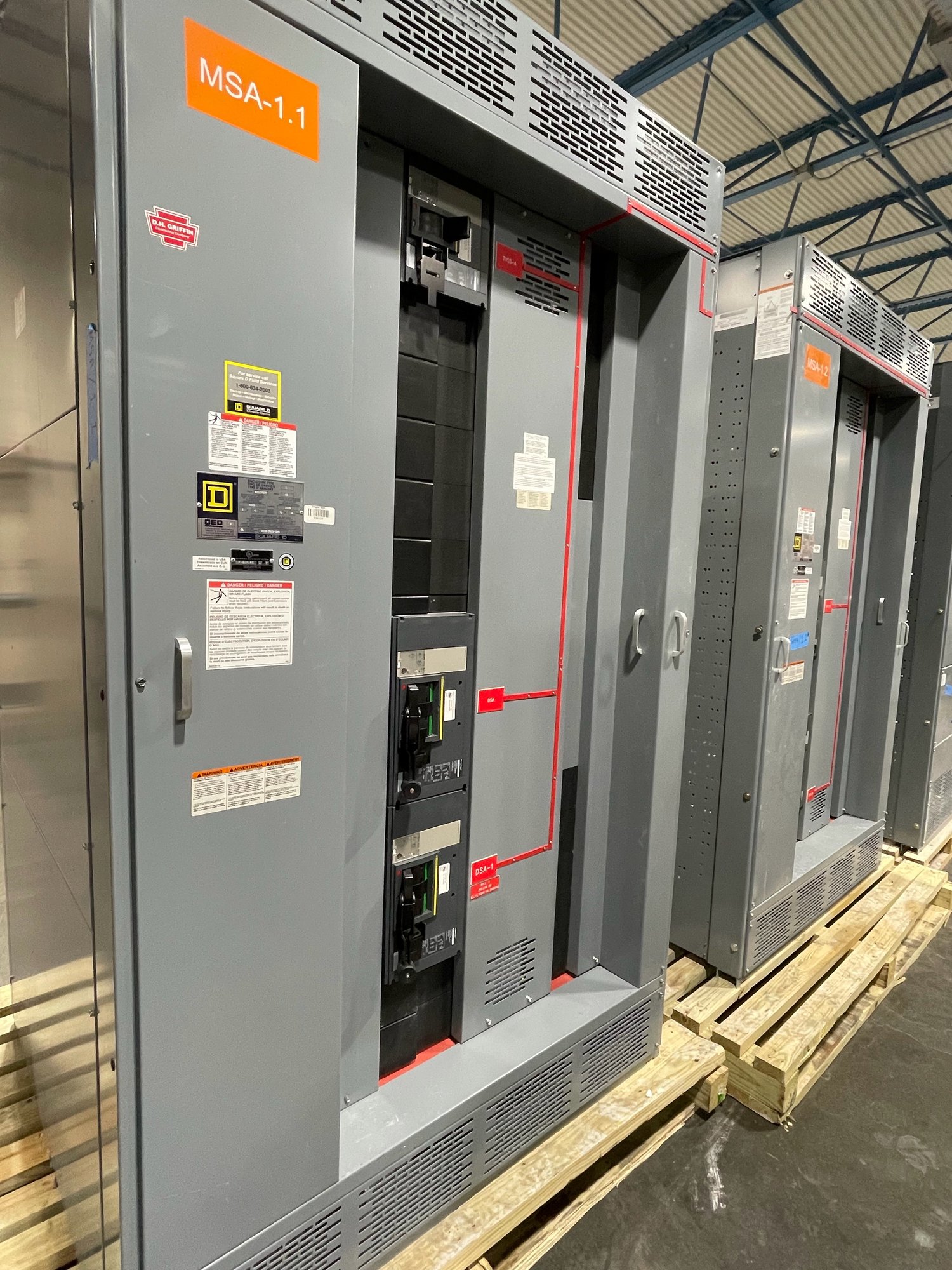
Define the test boundary
Start by identifying which switchboard devices participate in the network: protective devices, meters, gateways, controllers, or other specified equipment. Establish the boundary between factory-assembled wiring and external systems such as a building management system, supervisory control platform, or utility connection. Testing can confirm only the interfaces and functions included in the agreed scope.
Before quoting, share the one-line diagram, network architecture, device schedule, communication protocols, point list, and relevant sequences of operation. Note which equipment is furnished in the switchboard and which is supplied or configured by others. These details clarify required test access, responsibility for external endpoints, and whether the test is factory-based, site-based, or split between both.
Verify addresses and device identity
Address checks compare each device’s configured network identity with the approved schedule. Depending on the design, this may include IP addresses, subnet settings, node or unit identifiers, device names, and protocol-specific addresses. Confirm that addresses are unique where required and that gateway routing or segmentation matches the project network plan; do not assume a standard address scheme across projects.
A useful record links each physical device and panel designation to its configured address and communication role. Procurement teams should resolve who supplies address assignments and credentials, and when they will be available. If the final site network plan is still pending, define which settings can be verified with temporary test values and which must remain open for site commissioning.
Check links and protocol exchange
Link testing examines the communication path at the interfaces included in scope. Depending on the specified media and protocol, checks may include connection status, device discovery, expected responses, and basic data exchange between a device and its intended peer. A link indicator alone does not demonstrate that application data is correct or that the complete site network is available.
The test plan should name the protocol, physical interface, endpoints, and any required test equipment or network access. Identify constraints such as customer-managed switches, cybersecurity rules, unavailable upstream systems, or proprietary configuration files. For equipment shipped to Georgia, agree whether external links can be simulated or must be verified after installation; delivery does not itself confirm an end-to-end connection.
Validate signal mapping and values
Signal mapping checks that specified points appear under the expected names and are associated with the correct source and destination. Review the point list for status, measurement, and alarm signals, including scaling, units, polarity, and normal or asserted state where applicable. A point can communicate successfully while still representing the wrong device, value, or condition.
Use approved drawings and the current point schedule as the test reference, and document exclusions or unresolved points rather than silently substituting assumptions. Ask who owns edits to the list and whether revisions after testing require retest. Where physical conditions cannot be created during assembly, distinguish a verified mapping or simulated input from a demonstrated field response.
Confirm clock alignment and alarm delivery
Time synchronization matters when event records from multiple devices must be compared. Confirm the intended time source, protocol or method, time zone, daylight-saving treatment, and expected behavior if the source is unavailable. Testing can verify configuration and observed alignment under the available setup, but a temporary test network may not prove synchronization through the customer’s final infrastructure.
Alarm checks follow selected conditions from source device through configured communications to the designated receiving point. Verify the expected point, text or identifier, state transition, and any specified reset behavior. Clarify whether a receiving system, notification service, or remote operator interface is included; alarm delivery cannot be confirmed beyond an endpoint that is accessible and authorized for the test.
Set acceptance records and handoff
Agree on acceptance criteria before testing: devices and points in scope, test method, required evidence, treatment of unavailable interfaces, and how discrepancies will be handled. A practical report can identify the device, address, link or point tested, result, test conditions, exceptions, and outstanding action. Keep results tied to the applicable drawing and configuration revision so later changes can be evaluated accurately.
For a Georgia project, provide the ship-to location, required delivery sequence, site access constraints, and the date when external network resources are expected to be available. Exact scope, component availability, and schedule are confirmed for each order. Before requesting a quote, send the network architecture, device and point schedules, protocols, time-source requirements, alarm destinations, and preferred handoff format; use that information to define a test plan that can be completed and reviewed.