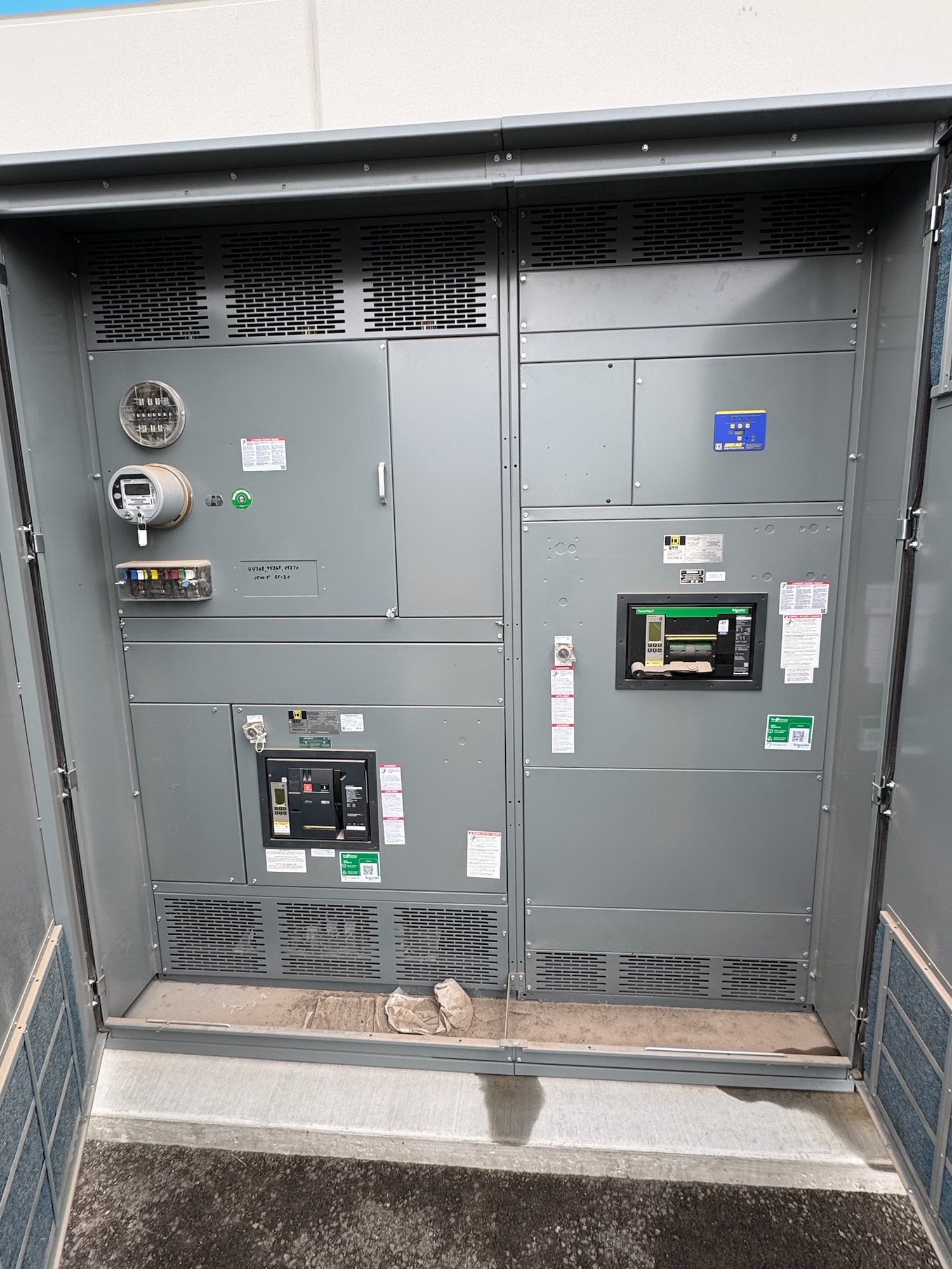
Start with the approved point list
The point list defines what the test must prove. For every alarm or status point, it should identify the source device, displayed label, normal and alarm states, local annunciator or meter indication, remote destination and expected signal behavior. References should align with the current one-line diagram, control schematics, equipment tag schedule and communications documents. If these records disagree, resolve the discrepancy before testing rather than improvising a pass criterion at the panel.
Confirm the list’s revision and approval status with the project engineer or controls lead. Ask whether points are hardwired, communicated through a network, or divided between both methods; whether alarms are latched or self-resetting; and whether acknowledgement, reset or return-to-normal indications are required. Identify spare, disabled, suppressed or out-of-scope points explicitly. These decisions keep test results tied to the intended design instead of an assumed configuration.
Define what local annunciation means
Local verification may include an illuminated indicator, text display, audible device, relay indication or another specified operator interface. Check the exact point label and its location, then confirm that the intended alarm condition produces the expected visual and audible behavior. Where the design requires acknowledgement or reset, verify those actions and confirm that they do not falsely clear a condition that remains active. The approved sequence, not a generic annunciator convention, sets the acceptance criteria.
Testing must be planned around the equipment’s approved test method and the project’s safety controls. A qualified technician should use authorized simulation or test provisions, with the equipment in the agreed condition and operations personnel informed of affected alarms. Avoid creating a real electrical fault to prove an indication. If a point cannot be safely simulated or its behavior is unclear, record the limitation and obtain engineering direction before proceeding.
Verify the remote path end to end
A correct local lamp does not prove that a control room, building management system or other remote destination receives the right signal. Trace each listed point to its specified endpoint and verify the displayed tag, state and any required alarm priority or text. For networked points, confirm the intended mapping and state interpretation; for hardwired points, verify the designated input and normal-versus-alarm convention under the approved procedure. Include loss-of-communications indications only when they appear in the project scope.
Coordinate remote testing with the controls integrator and the personnel responsible for the receiving system. Agree on a test window, the affected screens or notification routes, and how test events will be distinguished from live operating alarms. If a signal is not visible, isolate the issue by checking the source state, interface mapping and receiving point without changing settings outside authorized control. Record who observed the remote indication and what evidence supports the result.
Set boundaries before procurement
When requesting a quote for new switchgear or an associated test scope, provide the approved point list, relevant control drawings, alarm narrative and required test deliverables. State whether verification covers local devices only or includes remote interfaces, who supplies and configures the receiving system, and who provides qualified field personnel. Also identify the planned test stage, access constraints, required witness parties and any points that must remain inhibited or unavailable during the work.
Clarify the boundary between factory checks, site functional testing and commissioning. Factory verification can address functions available in the supplied assembly and agreed test setup; it cannot establish the operation of a customer’s remote system unless that interface is included and accessible. Confirm exclusions, test prerequisites, revision control and responsibility for resolving discrepancies. Exact configuration, availability and schedule are confirmed for each order, so procurement should compare scope and assumptions as well as equipment descriptions.
Plan the Georgia project handoff
For a Georgia installation, align delivery and testing milestones with the project’s receiving, storage, installation and commissioning sequence. New switchgear can be configured to the approved project requirements, and nationwide shipping can support delivery to the designated Georgia site; routing, timing and handling details depend on the order and destination. Have the receiving team verify shipment condition and equipment identification, then keep the point-list revision and test records with the project turnover documents.
A useful closeout package identifies each point, test method, expected result, observed local result, observed remote result, pass status, date, witness and open issue. Note any deferred test, approved limitation, changed label or corrective action, and link it to the responsible party and next verification step. Before handoff, reconcile the final point list with as-built drawings and the controls database so operators receive a usable record rather than a collection of untraceable test marks.
Turn results into an actionable record
A complete functional test demonstrates the signal path specified for each point: the intended condition is represented locally, transmitted through the designed interface and recognized at the assigned remote destination. A mismatch can reveal a labeling error, reversed state convention, missing mapping, failed device or unresolved design change. Classify findings by point and system boundary, and avoid declaring overall completion while required points remain untested or acceptance criteria remain unsettled.
Before requesting pricing, share the current approved point list and drawings, identify local and remote endpoints, describe the required test stage, and state witness and documentation needs. Ask the project engineer to settle ambiguous alarm states or reset behavior first. This preparation gives the manufacturer a defined scope to review, supports a more useful proposal for Georgia delivery, and leaves the project team with clear test responsibilities and handoff evidence.