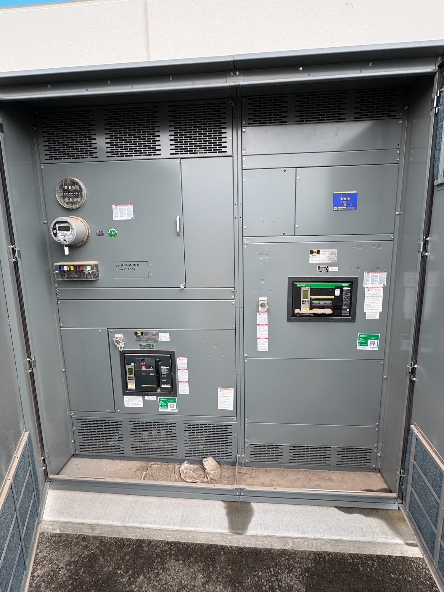
Choose the point of protection
Start by identifying which equipment needs protection and where the SPD will connect. A device at the service entrance can address surges entering the facility, while a downstream device may be appropriate for a particular distribution panel or sensitive load. The right arrangement depends on the system, exposure, existing protection and equipment being served; one location does not automatically protect every circuit equally.
Share a one-line diagram or describe the service and distribution sequence, including the intended connection point. Note whether the SPD is to be incorporated into a switchboard or supplied as a separate, coordinated component. This lets the equipment configuration reflect the design intent rather than assuming a location that may conflict with conductor routing, barriers or available space.
Specify ratings for the actual system
The SPD must be selected for the electrical system and its connection. Key information includes nominal voltage, phase and wire configuration, grounding arrangement, available fault current at the connection point, and whether the device is intended for service entrance or downstream use. Specify the desired voltage protection level and surge current ratings in line with the project’s engineering requirements and applicable product documentation.
Do not select a rating based only on a broad description such as “standard service” or “high surge.” Confirm the system’s maximum continuous operating voltage, expected exposure, and any requirements set by the engineer, owner or authority having jurisdiction. If the electrical data is incomplete, identify what remains unconfirmed so the design team can resolve it before the SPD and distribution assembly are finalized.
Coordinate the disconnect and connection path
An SPD may have an integral disconnect or require an external overcurrent protective device, depending on its design and the installation requirements. Confirm the manufacturer’s instructions for protection, conductor size and permitted connection method. The disconnect must suit the specified device and system; it should not be treated as an interchangeable accessory selected without reviewing the documentation.
Connection length and routing matter because the conductors between the SPD and the protected bus contribute to the installed protection path. Ask the design team to identify the intended connection point and practical routing before enclosure layouts are released. Bus access, conductor bends, barriers and separation from other components can affect whether the proposed arrangement is workable within the available equipment space.
Plan for inspection and replacement
An SPD needs a location where qualified personnel can inspect its status indicators and reach its disconnect without dismantling unrelated equipment. Consider door access, working space, adjacent gear and the installed orientation. If a replaceable module is part of the selected design, allow for its removal path and confirm whether the replacement procedure requires isolation of the device or a larger portion of the distribution system.
Include the owner’s maintenance expectations in the specification. Identify who will inspect the device, how status will be monitored, and whether remote indication or alarm contacts are required and available on the selected model. Clear access and a defined maintenance approach help prevent a device from becoming difficult to evaluate after commissioning.
Resolve enclosure and assembly constraints
Integration depends on the complete assembly layout, not just the SPD’s catalog dimensions. Provide enclosure type and location, environmental conditions, available mounting area, cable or bus entry direction, and any space limitations imposed by the room. Where the SPD is installed within a switchboard, coordinate its position with the assembly arrangement and the need to keep inspection and service access practical.
UL 891 applies to switchboard assemblies; it is not a blanket listing for medium- or high-voltage switchgear. The project team must establish the applicable equipment scope, component suitability and approval requirements. Final design and installation decisions require review by qualified engineering personnel and the authority having jurisdiction; do not infer code compliance from an SPD rating or enclosure arrangement alone.
Prepare the quote and project handoff
For a useful quote, provide the project location in Georgia, requested equipment type, one-line diagram, system voltage and grounding details, intended SPD connection point, specified ratings, disconnect requirements, enclosure constraints and desired indication features. Include project milestones and shipping destination so the proposed build and delivery can be coordinated with the installation schedule. Exact scope, component availability and timing are confirmed for each order.
Before release, have the project team verify the selected SPD model, ratings, disconnect arrangement, conductor routing, access clearances and interface with the distribution assembly. Keep the approved submittal and manufacturer instructions with the commissioning and maintenance documents. For Georgia delivery, confirm site access, receiving arrangements and the required arrival window early; this helps align equipment shipment with site readiness without assuming a fixed transit time.