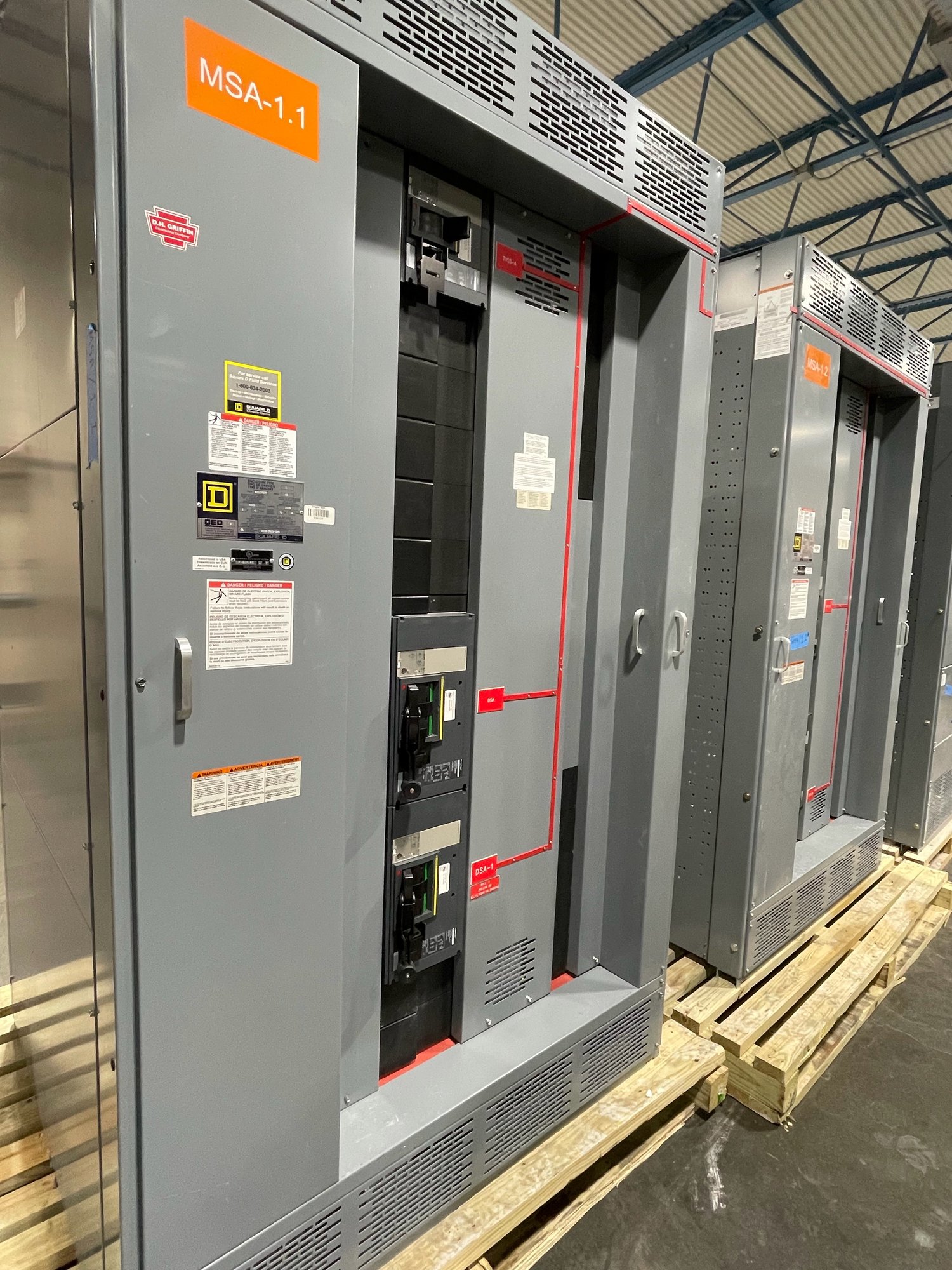
Start with the metering arrangement
Clarify what the current transformers (CTs) will serve and who specifies, furnishes, installs and connects them. Utility-owned revenue metering, customer-owned metering and protective relaying can require different compartments, wiring boundaries and access provisions. Do not assume that a familiar arrangement from another facility will satisfy the serving utility’s current standards.
Identify the service type and available project data, including system voltage, phase, frequency, service entrance arrangement and expected conductor or bus configuration. Provide the one-line diagram and any utility service requirements that show CT location and metering interfaces. These details establish the design basis; they do not by themselves determine final equipment ratings or approval.
Define cabinet space and access
CTs need room for their physical dimensions, mounting method, primary conductor path, secondary wiring and required clearances. The cabinet layout must also account for barriers, terminal blocks, test provisions, conduit entry and access for installation or inspection. Send CT drawings or dimensional data when available, including window size, orientation and terminal location; if the utility selects the devices, identify that as an open coordination item.
Review how the compartment will be reached and how conductors will enter, bend and pass through the CT openings. Bus or cable placement, compartment depth, adjacent sections, doors and removable covers can constrain the layout. The manufacturer can evaluate a proposed cabinet arrangement against the supplied equipment envelope, but utility requirements and the approved project design govern the final metering configuration.
Coordinate secondary wiring interfaces
Document the intended CT secondary connections, terminal-block arrangement, wire routing and destination of the metering circuits. Confirm whether the utility requires a particular test switch, shorting arrangement, sealable access, terminal identification or separation from other control wiring. These are interface questions for utility review, not details to infer from a generic switchboard drawing.
Make ownership and installation boundaries explicit. A responsibility matrix can identify who supplies CTs, secondary wiring, test devices, meter socket or enclosure, conduit and final terminations. It should also show who reviews wiring diagrams and who performs testing or commissioning. CT secondary circuits require qualified handling under the approved procedure; the equipment proposal should not substitute for project-specific instructions.
Resolve utility and manufacturer reviews
Request the serving utility’s applicable metering standards, service manual excerpts and project-specific comments before the configuration is finalized. Confirm required compartment location, enclosure access, dimensions, seals and any drawings or submittals needed for acceptance. Requirements can vary by utility and service arrangement, so a prior project or standard cabinet should not be treated as automatic approval.
At the same time, the manufacturer reviews the requested features against the switchboard design and available space. Changes to section width, bus arrangement, barriers, access panels or wiring routes may affect the overall configuration. UL 891 applies to switchboard assemblies within its scope; it is not a blanket certification for every component, metering arrangement or system voltage. Final design and acceptance remain subject to applicable engineering and authority review.
Prepare a quote-ready package
For a useful quotation, provide the one-line diagram, utility requirements, service data, CT dimensional information if selected, metering schematic, desired cabinet location and project schedule. Include installation constraints such as room access, lineup dimensions, cable approach and conduit entry. State which details are confirmed and which are pending utility direction so assumptions can be identified instead of hidden in the proposed layout.
Purchasing teams should compare proposals on the stated scope: supplied CTs or customer-furnished devices, compartment construction, metering interfaces, drawings, exclusions and required review milestones. Ask how unresolved utility comments will be handled before release. Availability, configuration and production timing are confirmed for each order; early, complete inputs help expose design questions before they affect procurement planning.
Plan the Georgia project handoff
For delivery to a Georgia project, coordinate the approved lineup dimensions and shipping configuration with the receiving route, unloading plan, indoor storage conditions and installation sequence. Confirm the delivery destination, receiving contact, site access limits and required delivery window when requesting a quote. Nationwide shipping can support Georgia projects, while the exact shipment plan and timing are confirmed for the specific order.
Before authorizing production, circulate the final metering layout and interface drawings to the utility, engineer, contractor and purchasing team as applicable. Record approved CT dimensions, wiring boundaries, access requirements and any outstanding approval conditions. Then submit the confirmed project documents with the quotation request so the proposed cabinet integration can be evaluated against both the switchboard design and the utility’s stated requirements.