What solid grounding means
In a solidly grounded system, the source neutral connects directly to the grounding system without an intentional resistor or reactor in that connection. The connection establishes a reference to ground and provides a path for current during a ground fault. It does not mean fault current is small, nor does it make a ground fault harmless.
The system’s behavior depends on its source, voltage, transformer winding connections, conductor paths, and fault location. A grounded-wye source may support substantial current when a phase conductor contacts grounded metal. By contrast, an ungrounded or impedance-grounded arrangement behaves differently. Confirm the actual grounding method and source configuration rather than inferring them from a panel schedule or nominal voltage.
Ground-fault current and its path
A phase-to-ground fault can return through equipment grounding conductors, bonding connections, raceways, and the source grounding point. The current available at the fault is influenced by source impedance and the impedance of that complete loop. A bolted fault near a transformer may produce a different value from a fault farther downstream, where longer conductors add impedance.
Engineers need calculated ground-fault current at relevant points, not just a general statement that the system is solidly grounded. The study should identify the source and transformer data, conductor lengths and sizes, system configuration, and operating modes that affect the result. Those values inform interrupting ratings, protective-device settings, and coordination; they should not be guessed from the grounding method alone.
Protection must detect and clear the fault
A solidly grounded system can produce enough ground-fault current to operate phase overcurrent protection, but that outcome depends on the fault magnitude and device settings. Smaller or remote faults may not produce the same response as a high-current fault close to the source. The protection study should check that the selected devices detect expected fault levels and clear them within the intended coordination scheme.
Ground-fault sensing may use residual current from phase sensors, a zero-sequence sensor around the phase conductors, or another scheme suited to the equipment and system. Sensor placement, neutral routing, polarity, relay functions, trip settings, and breaker capabilities all matter. Define which devices require ground-fault protection and how they interact with upstream and downstream protection; the engineer must verify the scheme against the applicable design and authority requirements.
Specify the switchgear around the study
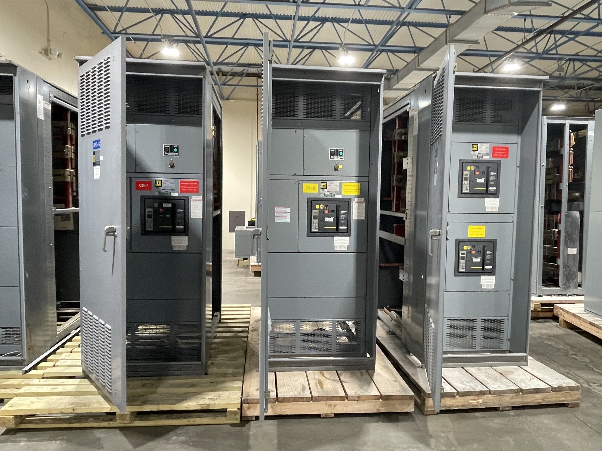
For a new switchboard or switchgear package, provide the one-line diagram, system voltage and frequency, available fault-current study, source and transformer information, grounding arrangement, and required device functions. Identify incoming and feeder breaker or switch requirements, sensor arrangements, metering, control power, and any neutral switching or monitoring needs. These details let the equipment configuration reflect the design rather than an assumed standard arrangement.
Ask whether the proposed assembly and devices can accommodate the specified fault-duty and protection scheme, and identify any assumptions that still require engineering confirmation. UL 891 applies to switchboard assemblies; it is not a blanket listing for medium- or high-voltage switchgear. The applicable equipment standard, ratings, and assembly scope should be confirmed for the actual product and project.
Coordinate drawings, settings, and handoff
Grounding and protection decisions must carry through from the one-line diagram to equipment drawings, device schedules, and field settings. Before release, reconcile the device types and sensor locations with the latest study and confirm that neutral and grounding conductors are represented correctly. Changes to transformer data, feeder routing, or operating modes can alter fault current and may require a revised study or equipment review.
For procurement, ask what information is needed to confirm the configuration, what drawing review and approval steps apply, and which project inputs remain open. Share the Georgia delivery location, requested delivery window, receiving constraints, and site access requirements so shipping can be planned for the project. Availability, final scope, and timeline are confirmed for each order; delivery planning does not replace engineering review or qualified installation and commissioning.
Prepare a useful quote request
A practical request should state whether the equipment is a new installation or a modification within a broader project, the system voltage, source arrangement, solid-grounding details, available fault-current values, and required protective functions. Include the one-line diagram, equipment schedule, preferred device and sensor details, enclosure or installation constraints, and any applicable project specifications. If a study is pending, identify the data still to be established instead of presenting estimates as final.
Before requesting a quote, assemble the latest engineering documents and list unresolved decisions about fault duty, ground-fault sensing, trip functions, coordination, and assembly scope. Ask for review of the requested configuration against the supplied information, then route design questions and settings to the responsible engineer. This gives the manufacturer a clear basis to define new equipment and gives the project team a focused list of items to close before approval.