Choose the grounding approach around the system
In a resistance-grounded system, a grounding resistor connects the source neutral to the grounding system. Its resistance establishes the available ground-fault current within the limits selected by the engineer. The approach can reduce damaging fault current compared with a solidly grounded arrangement, but it does not eliminate fault energy or the need for coordinated protection and safe work practices.
The first design question is whether the system is intended for low-resistance or high-resistance grounding, and what operational objective drives that choice. Low-resistance grounding commonly supports prompt fault detection and clearing; high-resistance grounding may be considered where continued operation through an initial ground fault is part of the engineered operating plan. Voltage, source configuration, system capacitance, protective-device coordination and applicable project requirements all affect selection.
Define resistor and neutral details
A useful specification identifies system voltage, frequency, source and transformer winding arrangement, neutral availability, and the intended grounding point. The engineer should establish the resistor current and time rating, insulation requirements, enclosure and installation environment, and any monitoring or indication functions. These values must come from the system study and governing project requirements, not from a generic equipment description.
Confirm how the grounding resistor connects to the source and how conductors route between the neutral, resistor and grounding system. Ask whether the design includes one source or multiple sources, transfer or tie operation, and any operating states that could leave a source without its intended neutral-ground connection. Switching arrangements can change the grounding path, so drawings and control sequences should show which source is grounded in each permitted configuration.
Plan monitoring for useful fault information
Ground-fault monitoring should make the selected grounding method observable to operators. Depending on the design, functions may include resistor continuity supervision, ground-fault detection, alarm indication, and signals to a control or supervisory system. Specify what condition each alarm represents, where it is displayed, whether remote indication is required, and how the signal behaves during source transfers or loss of control power.
For high-resistance-grounded systems, a first ground fault may be alarmed rather than immediately tripped when the engineered design permits continued operation. That choice requires a defined response: personnel need to recognize the alarm, locate and isolate the fault under approved procedures, and understand what operating restrictions apply while it remains. Do not assume that monitoring alone locates a fault or makes continued operation acceptable; confirm detection method, coverage and response requirements with the engineer.
Coordinate equipment and protection interfaces
Grounding equipment must coordinate with switchgear, transformers, protective relays, metering and plant controls. Provide one-line diagrams, control schematics, available fault information and the intended trip or alarm logic during quotation and design review. Identify any required interface terminals, communications protocols, interlocks or annunciation points, while leaving final settings and protective decisions to the responsible engineering team.
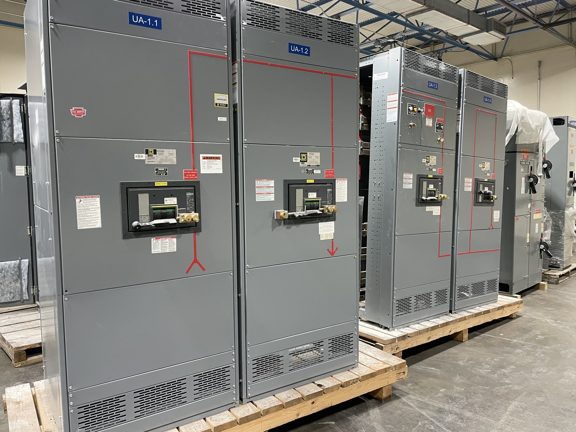
UL 891 applies to switchboard assemblies; it is not a blanket listing for medium- or high-voltage switchgear or grounding equipment. State the equipment type and requested standards or project specifications for each assembly, and have the engineer and authority having jurisdiction review the complete application. The manufacturer can confirm the offered configuration and documentation for the specific order, but project suitability depends on that review and the complete system design.
Prepare a complete procurement handoff
For a quote, share the one-line diagram, nominal voltage and frequency, source and transformer details, grounding method, resistor current and time requirements if established, enclosure conditions, monitoring points, and required drawings or submittals. Include the project location in Georgia, site access or delivery constraints, requested delivery window, and coordination dates for switchgear or other equipment. If a design value remains open, identify who will resolve it and when rather than treating an assumption as final.
Before release, align approved drawings, connection points, alarm and trip behavior, labels, and responsibilities for field wiring and commissioning. Exact scope, availability and schedule are confirmed for each order; Georgia delivery is coordinated to the project’s receiving and installation sequence, with nationwide shipping available. Ask the engineer to close grounding and protection decisions, then provide the approved documents and delivery requirements for configuration review.