Start with the point of interconnection
The interconnection location shapes the equipment scope. A PV system may connect at the service equipment, a distribution switchboard, or a downstream panel, subject to the project’s electrical design and utility requirements. Identify the proposed connection bus, the PV output circuit, the existing service arrangement, and any planned changes to loads or transformers. A one-line diagram is the clearest starting point for reviewing how generation and utility power reach building loads.
For a quote, provide the latest one-line, equipment schedules, site voltage and phase, service rating, PV inverter output data, and the intended point of connection. Include available fault-current information when established, plus known constraints on footprint, cable entry, and access. These details allow the proposed new assembly to be considered within the actual distribution arrangement rather than as an isolated equipment replacement.
Verify backfeed capacity before selecting equipment
Backfeed capacity is not simply the unused portion of a switchboard’s ampere rating. The engineering review must account for bus ratings, source and load current paths, overcurrent-device locations and ratings, applicable equipment limitations, and the proposed PV output. The permitted connection method and any required calculations depend on the existing design and the authority having jurisdiction. Do not assume that a main breaker rating alone establishes available PV capacity.
Share the equipment nameplates, breaker or fuse data, bus information, and prior modifications where available. If records are incomplete, arrange for qualified personnel to verify field conditions and reconcile them with drawings. The engineer of record determines the acceptable interconnection and protection design. A manufacturer can build a new switchboard assembly to the approved project specification, but cannot establish capacity from incomplete information or replace engineering and authority review.
Define isolation and operating boundaries
PV integration requires a clear account of how each source can be isolated for operation and maintenance. Identify the inverter output disconnecting means, the distribution device that separates the PV circuit from building buses, and the service disconnecting arrangement. Consider whether maintenance, testing, or an emergency condition could leave a bus energized from another source. Equipment labels, device locations, and the project’s operating procedures should align with the approved drawings.
Ask the design team to identify which devices must be accessible, how isolation will be achieved, and whether the new assembly needs dedicated compartments or a specific feeder arrangement. Confirm who is responsible for utility-required disconnect provisions and labeling. The final configuration depends on the system design and applicable review; installation, operation, and service belong to qualified electrical personnel following approved procedures.
Coordinate protection, metering, and physical fit
The PV source can affect protective-device coordination and metering, so review more than the available breaker space. Confirm the inverter’s output characteristics, proposed overcurrent protection, grounding and bonding approach, metering boundaries, and any monitoring interfaces required by the design. The engineer should evaluate fault-current contributions and protective-device performance for the complete system. The switchboard specification should reflect that coordinated design, including device types and ratings selected by the responsible engineer.
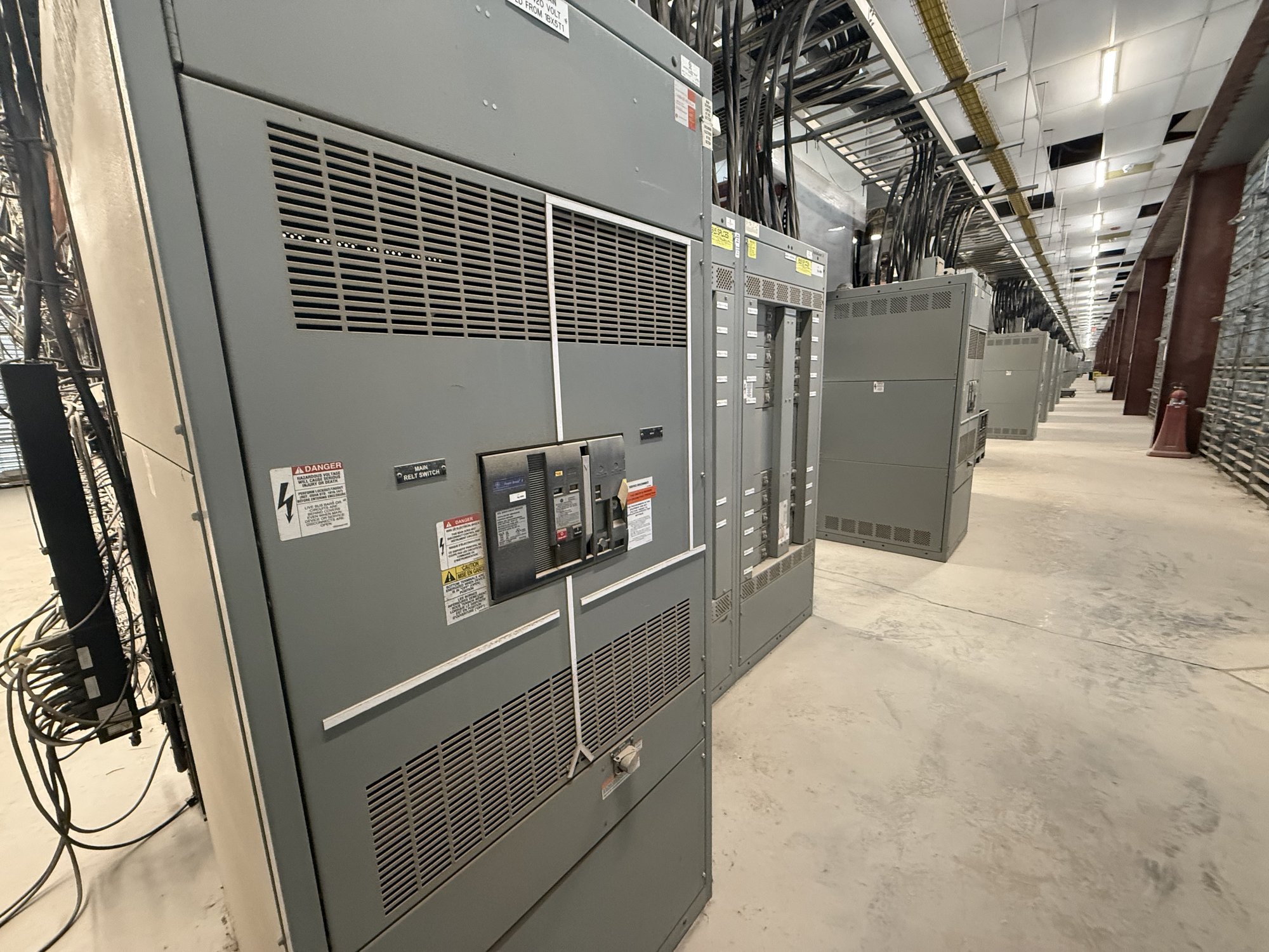
Physical constraints matter as well. Document existing lineup dimensions, working-space limits, cable routing, conductor entry, environmental conditions, and any restrictions on moving or replacing equipment. For a custom-built UL 891 switchboard assembly, the project documents should clearly state the intended application and required configuration. UL 891 applies to switchboard assemblies; it does not certify medium- or high-voltage switchgear or establish that a complete PV installation is approved.
Prepare a buildable procurement package
A focused procurement package reduces ambiguity between design intent and the delivered assembly. Include the approved one-line and elevations, bus and short-circuit requirements, device schedule, control and metering needs, cable-entry details, and interface points with the inverter and existing equipment. State whether the work is a new lineup, an addition, or a replacement, and identify scope boundaries for field connections and commissioning. Open items should be listed explicitly rather than left to assumption.
We manufacture new switchgear and switchboard equipment in the United States, using American-made components as project scope permits, and can build custom configurations. Availability, exact scope, and schedule are confirmed for each order. For Georgia projects, share the delivery site, access or receiving constraints, required delivery sequence, and target installation window so shipping and equipment planning can be coordinated without assuming a fixed transit time.
Hand off with clear project responsibilities
Before release for manufacture, confirm that the responsible engineer has resolved backfeed capacity, protection, isolation, and utility interface requirements. Ensure the approved drawings identify device functions, ratings, connection points, and any field-installed components. Procurement should compare the proposal against that package and record approved deviations. Changes to inverter output, service equipment, or interconnection location after design review may affect the assembly and should be routed back through the engineering team.
For a practical quote request, send the one-line, equipment data, PV inverter information, required switchboard configuration, site and delivery details, and the project decision schedule. Identify missing records and unresolved approvals openly. This gives the manufacturer a defined basis to review the requested new equipment and confirm scope and timing. Keep the capacity calculation and final interconnection approval with the project’s qualified engineer and applicable authorities.