Map the power paths first
Start with the one-line diagram and identify every source and destination: battery inverters, any photovoltaic or generator inputs, facility distribution, and the utility interface. The arrangement determines whether inverter outputs combine on a common bus, feed separate sections, or connect through dedicated transformers and protective devices. A switchboard should reflect the actual operating topology rather than assume a conventional utility-to-load sequence.
Document normal power flow as well as intended operating modes. A storage system may charge from the grid, discharge to serve site loads, or export under an approved interconnection arrangement. Provide the expected modes, source combinations, and points of isolation so the design team can evaluate switching and protection interfaces. Final operating logic and settings require coordination by the project’s qualified engineers and the utility.
Define ratings and protection interfaces
For each connection, establish the system voltage, phase and frequency, inverter output current, and anticipated fault-current contribution. Utility source data, transformer impedance, conductor details, and other connected sources affect available fault current at the switchboard. Do not select interrupting ratings from inverter output current alone; the engineer of record must establish the applicable values and confirm device suitability for the installation.
Specify the protective-device arrangement and the boundaries between inverter controls, switchboard devices, and upstream utility equipment. Relevant questions include which breakers provide isolation, whether main and feeder devices require adjustable trip functions, and what auxiliary contacts or shunt-trip interfaces the control scheme needs. Protection coordination, grounding, interconnection functions, and utility requirements should be resolved by the responsible engineering team, not inferred from a product description.
Coordinate bus layout and operating access
The lineup configuration depends on inverter count, feeder grouping, incoming and outgoing cable routes, and space for metering or control components. Share the one-line diagram, equipment arrangement, conductor entry direction, and available electrical-room dimensions. Identify whether future inverter blocks are planned; reserving a section or bus extension point can affect the initial structure and should be reviewed before fabrication.
Plan for operators and qualified service personnel to identify and isolate the intended section without confusing battery-side, load-side, and utility-side connections. Device labels, compartment arrangement, status indication, and control interfaces should follow the project documents and operating procedures. Confirm working clearances and access conditions with the project design team and authority having jurisdiction; the equipment supplier cannot determine site compliance from the lineup request alone.
Resolve metering, controls, and utility boundaries
Storage projects often need metering at more than one boundary: inverter output, facility load, and the utility point of interconnection may each serve a different control or reporting purpose. Specify meter locations, instrument-transformer requirements, communication protocols, and who furnishes each component. Confirm whether the switchboard must provide mounting and wiring provisions or whether metering belongs in separate equipment.
Clarify the signals exchanged with the energy management system, inverter controls, and utility-required interface equipment. Interlocks, permissives, remote trip functions, and status points must match the approved control narrative and drawings. Provide the required interface list and identify the responsible parties for field wiring and final checkout. Utility acceptance and control settings remain project-specific and should be confirmed before equipment details are finalized.
Prepare a quote package for Georgia delivery
For a useful quotation, provide the current one-line diagram, system voltage, bus and feeder requirements, inverter quantities and outputs, available fault-current information, enclosure and environmental requirements, cable entry details, metering needs, and any specified device or control interfaces. Include the project schedule, drawing review milestones, and known site constraints. If a detail is unsettled, identify the decision owner and target date rather than treating an assumption as approved.
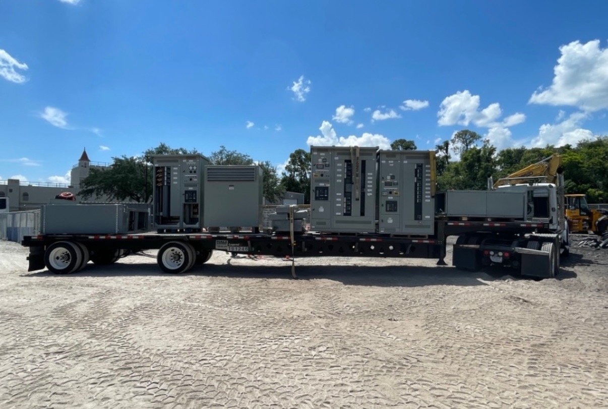
We manufacture new switchgear and UL 891 switchboard assemblies in the United States, with custom configurations and nationwide shipping. UL 891 applies to switchboard assemblies; it does not serve as a blanket listing for medium- or high-voltage switchgear. For a Georgia project, share the delivery location, receiving conditions, unloading plan, and required arrival window. Equipment scope, component availability, and production and shipping timing are confirmed for each order.
Carry design intent through release
Before release, reconcile the approved one-line diagram with the equipment schedule, breaker and bus data, metering arrangement, control interface list, and labeling plan. Confirm that changes to inverter count, utility requirements, or operating modes have been reflected in the documents. A controlled submittal review helps prevent mismatches between the switchboard, inverter package, protection scheme, and site wiring.
Start by sending the project one-line and listing the inverter outputs, site-load connections, utility boundary, required ratings, and delivery constraints. Identify open engineering decisions and the people responsible for resolving them. That information gives the manufacturer a defined basis to configure the distribution assembly and confirm scope, schedule, and Georgia delivery details with the project team.