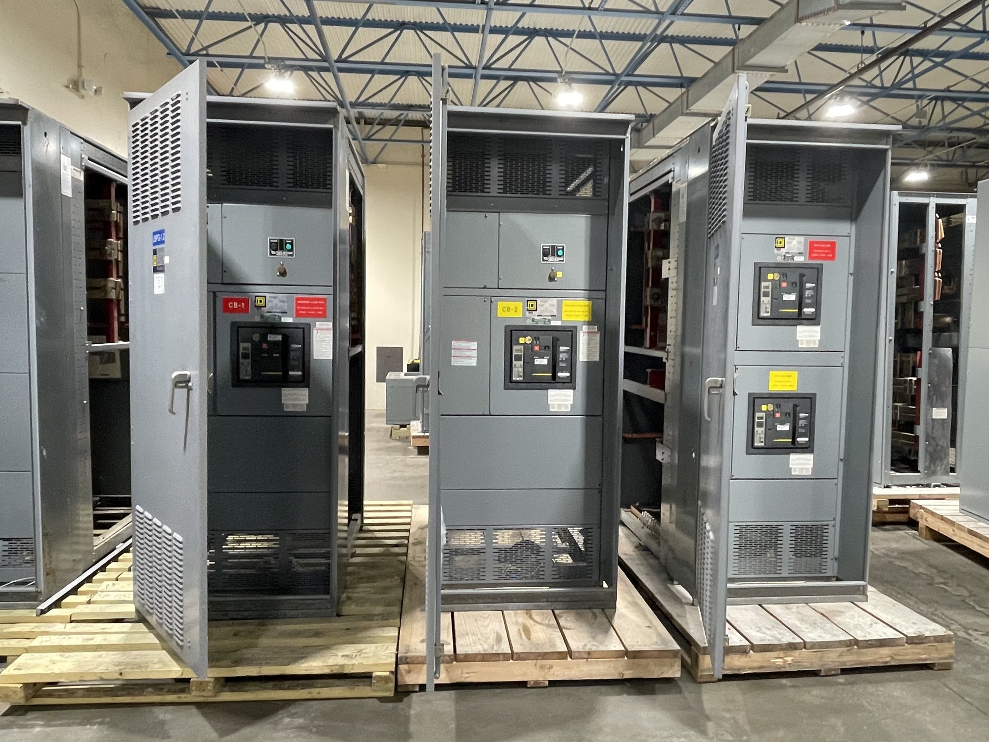
Start with essential services and operating priorities
Map the facility’s electrical loads by operational consequence, not just by building department. Dispatch consoles, radio and communications systems, network equipment, access control, emergency lighting, HVAC for critical rooms, and battery charging may have different continuity needs. Identify which loads must remain supplied, which can tolerate a brief transfer, and which may be shed during extended operation.
Confirm the expected operating scenario with facilities, dispatch leadership, electrical engineers and the authority having jurisdiction. A continuously staffed center may require different load grouping and restoration priorities than a support building used during incidents. Document normal and emergency operating modes, including whether critical functions depend on equipment in another building or on shared campus distribution.
Define the backup-power path
Describe how utility service, generator sources, transfer equipment and switchboard sections are intended to connect. The design team should establish source count, voltage, phase, system grounding, transfer method, fault-current assumptions and the locations of required isolation points. Switchboard configuration must coordinate with the project’s transfer equipment and protection scheme; it cannot be selected independently of the one-line diagram.
For generator-backed loads, clarify whether multiple units operate in parallel, whether a single generator serves an emergency section, and what happens if a source or transfer device is unavailable. Identify any required separation between essential and nonessential distribution, along with controls or interlocks that affect switching. Final equipment ratings, protection settings and operating sequences require engineering review for the actual system.
Specify distribution for dispatch continuity
Review how circuits are grouped so a fault, maintenance task or planned shutdown does not unnecessarily interrupt unrelated functions. Critical communications, information technology, life-safety systems and general building loads may call for distinct distribution paths, depending on the engineer’s design. Coordinate switchboard feeder spaces, breaker types and circuit identification with the downstream panels and equipment they serve.
Ask how operators will identify source status, circuit purpose and the boundaries of each section during an abnormal condition. Clear, durable labeling and a usable operating sequence support trained personnel, but labels must match approved drawings and field conditions. Consider access for inspection and maintenance, working clearances, cable entry, conduit routing and the room’s environmental conditions before fixing the lineup dimensions.
Resolve ratings, space and coordination early
Provide the latest one-line diagram, available fault-current information, load schedules, source data and project specifications when requesting a configuration. The engineer of record should define required interrupting and bus ratings, protective-device coordination, ground-fault provisions and any metering or communications requirements. Do not infer these values from a similar building; utility conditions and generator contributions can change the selection.
Check the electrical room plan for door openings, equipment access, aisle space, ceiling height, cable bend space and the intended installation path. A lineup that fits a drawing may still be difficult to move into an existing facility. Share renovation constraints, outage windows, phasing needs and any limits on disrupting dispatch operations so equipment sections and delivery sequencing can be evaluated against the project plan.
Make procurement and handoff deliberate
For a quote, share the project location in Georgia, required delivery window, quantity and scope, approved or current drawings, specification, voltage and source arrangement, known ratings, and the status of engineering review. Identify options that remain open rather than treating preliminary assumptions as final requirements. New switchboard assemblies built to UL 891 can be discussed where that standard applies to the specified switchboard; it does not establish a listing for medium- or high-voltage switchgear.
Confirm the agreed configuration, submittal review responsibilities, drawing revisions, shipment destination, receiving access and delivery sequence before release. Georgia delivery can be coordinated with the project schedule, site access limits and planned installation phase; availability and timing are confirmed for each order. At handoff, align approved drawings, equipment identification and required documentation with the installing contractor and facility team. Have qualified personnel perform installation, testing and energization under the project’s engineering documents and applicable authority review.