Define what the test must prove
A useful test plan begins with the protection functions and operating sequences the project expects to verify. Identify the relay types and functions, such as overcurrent, ground-fault, voltage, frequency or differential protection, only where they are part of the design. Clarify whether testing covers individual elements, combinations of functions, interlocking, alarms, control switches, communications, or a complete operating sequence.
The approved drawings, protection settings, logic diagrams and applicable project specifications determine acceptance criteria. Confirm which documents govern if settings or wiring information conflict, who approves revisions, and whether the test is factory-based or part of a broader commissioning plan. Testing can verify the configured response against supplied requirements; it does not replace engineering review of protection coordination or system suitability.
Plan relay input simulation
Input simulation applies representative current, voltage, contact status or other defined signals to relay inputs so the expected pickup, timing, indication and reset behavior can be observed. The test method depends on relay design, available terminals, wiring access and the functions being checked. Specify the required test points, signal ranges, polarities, phase relationships and operating conditions from approved documentation rather than assuming a generic test sequence.
For current- and voltage-operated functions, identify the expected thresholds and timing criteria, including any tolerances stated in the project documents or relay instructions. For binary inputs, state the required normal and operated states and any debounce or seal-in behavior that matters. Confirm whether the test is limited to relay terminals or includes field wiring and connected devices; those are different scopes and may require different access and coordination.
Verify logic and trip paths
Logic verification follows the path from simulated condition through relay elements, equations, permissives, blocks, timers and latches to the intended output. Test cases should cover expected operation as well as relevant restraint conditions, such as a blocked trip, missing permissive or reset sequence, when these behaviors are documented. A truth table or concise cause-and-effect matrix can help reviewers see which combinations must assert, inhibit or reset each function.
Trip-output checks confirm that the designated relay output changes state and reaches the specified interface, such as a breaker trip circuit, lockout relay, annunciator or control-system point. The test boundary must be explicit: observing a relay contact is not the same as proving the downstream device operates. State whether output circuits will be isolated, simulated or checked end to end, and coordinate any live-system restrictions before testing. Only qualified personnel should perform installation, testing or energization under approved procedures.
Resolve scope and procurement details
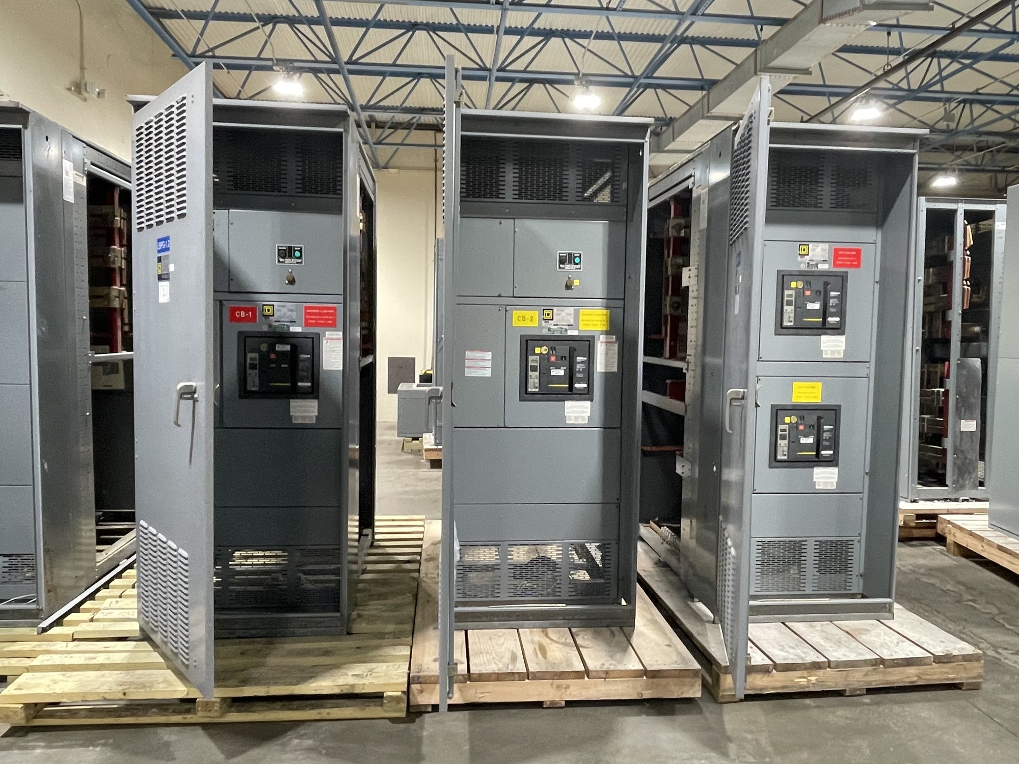
Before requesting a quote, share the relay make and model, quantity, protection functions, approved settings and logic files, relevant wiring and elementary diagrams, and the required test boundary. Include the switchgear lineup or assembly context, control-power details, output destinations, acceptance criteria, witness requirements and preferred test documentation format. Identify whether testing must be performed before shipment, at a project site, or as part of another defined service scope.
Also flag constraints that affect access or sequencing: relay firmware or configuration versions, available test switches, communications dependencies, restricted outage windows, customer-furnished procedures and any required coordination with other equipment. For new switchgear, provide the expected configuration and interface information early enough to evaluate how functional checks fit the build and release plan. Scope, availability and schedule are confirmed for each order; no assumed lead time should substitute for that project review.
Make records useful at handoff
A practical test record identifies the relay and its configuration, the controlling document revisions, test equipment and methods, applied inputs, expected results, observed results, pass or exception status, and the person responsible for recording the work. Include measured pickup or timing values when required by the acceptance criteria. Record any deviations, unresolved discrepancies and approved changes rather than silently revising the expected result.
The handoff package should let the commissioning team understand what was tested and what remains outside scope. Link exceptions to a drawing, function or test step; identify required corrective action and retest status; and preserve the final approved settings and logic revision. Agree on record format, review responsibility and delivery point before testing so results can be incorporated into project turnover without guesswork.
Coordinate Georgia project delivery
For Georgia projects, delivery planning should match the equipment release sequence, receiving location, site access rules and the time the project team needs to review test records. We build and supply new switchgear with custom configurations and can plan nationwide shipment, including Georgia destinations. The project team should confirm the destination, receiving contact, delivery constraints and whether test documentation is needed before shipment or at handoff; timing and availability depend on the order scope.
To start a focused quote, send the relay schedule, approved settings and logic, drawings, required test cases, output boundary, acceptance criteria, documentation expectations and target delivery sequence. Note any witness or site-coordination needs and identify the decision-maker for technical clarifications. With those details, the testing scope can be evaluated against the actual relay and switchgear configuration, and the project can agree on a documented path from simulated inputs to verified outputs.