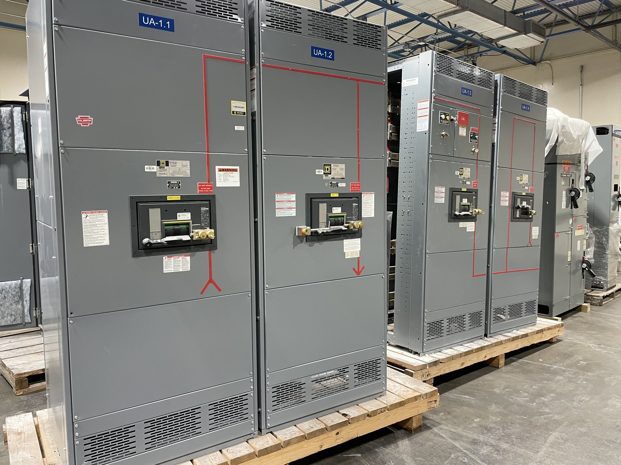
Why polarity matters in the protection circuit
A current transformer (CT) has marked primary and secondary terminals that establish its polarity reference. When current enters the designated primary terminal, the corresponding secondary current direction is defined by the CT’s markings. If the secondary leads are reversed, the magnitude may still appear plausible, but its phase relationship is inverted. That distinction matters wherever the signal is compared with voltage, another phase, or another CT.
Meters use CT signals to calculate quantities such as current, power and energy. Protective relays use them in functions such as differential, directional and ground-fault protection. Incorrect polarity can reverse a displayed or calculated quantity, defeat expected cancellation between CTs, or alter a relay’s operating direction. The result depends on the circuit and settings, so polarity is one part of a coordinated design review, not a substitute for relay testing.
Define the scope before specifying a test
A useful specification identifies each CT by switchboard section, feeder or phase, and shows the primary and secondary terminal designations. Include the applicable one-line diagram and wiring diagrams, CT ratio, accuracy or protection class, secondary rating, burden requirements and intended meter or relay connections. Note whether the project includes phase CTs, neutral or ground sensing, differential zones, or multiple secondary windings; each can have a different polarity-check scope.
Ask what evidence the project requires: verification of CT terminal markings, secondary lead continuity and identification, a polarity test at accessible terminals, or documented checks of the connected circuit. These are related but not interchangeable activities. The test method and acceptance criteria should be selected by qualified personnel for the CT design and project procedures. Confirm that drawings and device manuals agree before relying on a result.
What a polarity check can establish
A polarity test applies a known relationship at the CT primary and observes the resulting secondary indication using an appropriate method and instrument. The observation is compared with the CT’s marked terminals and the expected direction. For an installed circuit, checks may also trace the secondary conductors to terminal blocks, test switches, meters or relay inputs. The chosen procedure must account for whether the CT is installed, isolated or connected to other equipment.
A polarity result confirms a relationship at the points tested; it does not by itself prove the CT ratio, accuracy, insulation condition, burden suitability, relay settings or complete protection scheme. Nor does a correct CT marking guarantee that field conductors were landed correctly. Record the test points, CT identification, method, result and any discrepancy, then resolve mismatches against approved drawings before the circuit is accepted.
Protect people and connected equipment
CT secondary circuits require deliberate control during testing. An energized CT secondary must not be opened; an open circuit can produce hazardous voltage and damage equipment. Testing plans should identify the source condition, isolation boundaries, approved shorting provisions and the status of connected meters and relays. Only qualified personnel following site procedures and applicable equipment instructions should perform or supervise the work.
Polarity checks on new switchgear are best coordinated with the project’s inspection and commissioning plan. Establish who supplies test equipment, who controls switching, how relay inputs are protected during checks, and what documentation is needed for turnover. If a mismatch appears, do not correct leads by assumption: compare terminal markings, schematics and intended protection logic, then obtain engineering direction and repeat affected checks after the approved correction.
Coordinate switchgear configuration and procurement
When purchasing new switchgear, share the one-line diagram, CT schedule, metering and relay requirements, control schematics, and any project-specific test documentation requirements. Identify which CTs and secondary circuits are included in the supplied assembly and which connections or verification activities remain part of field installation. This helps clarify configuration, accessible test points, terminal identification and the handoff between equipment supply and site commissioning.
For a quote, provide the required CT ratios and classes, number of cores, conductor or bus arrangement, phase and ground-sensing needs, connected device information, project voltage and current requirements, drawings, delivery destination and requested schedule. Georgia delivery can be coordinated with the project’s receiving and installation sequence; exact configuration, availability and timing are confirmed for each order. UL 891 applies to switchboard assemblies, not as a blanket certification for every CT or for medium- or high-voltage switchgear.
Close the loop with usable records
A complete handoff connects the tested CT to its function. Test records should identify the equipment and circuit, show terminal references and measured or observed polarity, note the instruments and method used, and list unresolved exceptions. The commissioning team can then compare the as-tested wiring with the approved schematics, meter phase references and relay settings. Keep revised drawings aligned with any authorized wiring changes.
Before requesting a configuration or quote, gather the CT schedule, diagrams, connected-device requirements, test scope, site constraints and Georgia delivery details. Ask which polarity-related checks are included in the supplied equipment documentation and which belong to field commissioning. Resolving those questions early gives the engineer, installer and owner a clear basis for verifying that measured signals and protective functions follow the intended design.