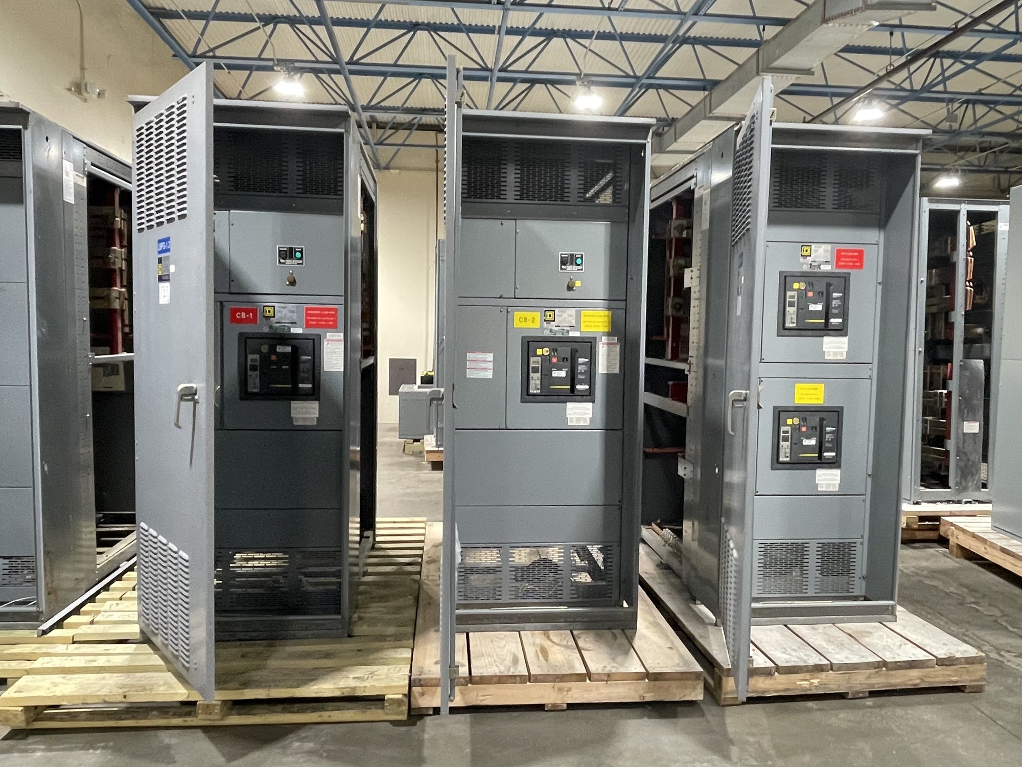
Define the sources and load
Start with a one-line diagram showing the normal source, alternate source, transfer equipment and loads supplied. Identify whether the sources are utility services, a generator, or another arrangement, and state which source normally carries the load. Include source voltage, phase, frequency, available fault-current information and grounding details for engineering review; do not infer compatibility from voltage alone.
Clarify whether the transfer device serves an entire switchboard section, selected feeders or a dedicated load. List the loads that must remain connected, those that may be shed, and any required separation between source circuits. A manual configuration is not a substitute for load analysis: the project engineer must establish equipment ratings and verify the proposed arrangement against the actual system and applicable authority requirements.
Choose the switching arrangement
A transfer arrangement may use a changeover device with defined source positions, or separate switching devices arranged so only the intended source can feed the load. The choice affects footprint, access, operating visibility and how the assembly integrates with upstream and downstream equipment. Specify whether the operator needs distinct normal, alternate and off positions, and whether an open transition is required.
Describe the operating sequence in practical terms. For example, should an operator disconnect the load from the normal source before closing the alternate-source path? Is a deliberate off position needed during transfer or maintenance? The answer depends on the system design and load behavior. Do not assume that momentary interruption, source overlap or parallel operation is acceptable; have the engineer define the permitted sequence.
Select an interlock strategy
Mechanical interlocking physically constrains device operation so a prohibited combination of switch positions cannot be selected through the linked mechanism. Electrical interlocking uses control-circuit conditions to inhibit an operation, often based on auxiliary contacts or other defined signals. These approaches address different failure paths, and an electrical interlock depends on its control-power and circuit design.
Ask the project engineer to identify which positions must be mutually exclusive and what should happen if control power is lost, a contact indication is unavailable, or a device cannot complete its travel. Confirm how the operator can verify position and whether the intended interlock arrangement fits the selected equipment. Interlocks reduce the chance of an unintended switching state but do not replace clear procedures, training or system review.
Write procedures around real conditions
Operating instructions should identify who is authorized to operate the equipment, how the operator confirms the available source, and what indications must be checked before and after a transfer. Include the expected position sequence, load conditions and steps for returning to normal service. The facility’s qualified personnel should review procedures for its actual operating practices and emergency plans.
Define how abnormal conditions are handled rather than relying on an operator to improvise. Examples include an alternate source that is unavailable, an unexpected trip, uncertain position indication or a load that does not tolerate interruption. The equipment configuration can support a specified sequence, but operating procedures must address site conditions, coordination with other equipment and any required lockout or maintenance controls.
Specify the assembly and handoff
For a quote, provide the one-line diagram, source and load data, device arrangement, required positions, preferred interlock method and any control or indication requirements. Also share enclosure and access constraints, cable-entry preferences, environmental conditions, project schedule and required submittal information. State whether the assembly is a UL 891 switchboard application; that standard applies to switchboards, not as a blanket certification for other voltage classes or equipment.
Review drawings for device orientation, operating access, labels, interlock logic and terminal or cable provisions before release. Identify who will approve the sequence and who will prepare site-specific operating documents. As a U.S. manufacturer, we build new switchgear and can evaluate custom configurations using American-made components; exact scope, availability and timing are confirmed for each order.
Plan Georgia delivery and closeout
For Georgia projects, coordinate the delivery destination, receiving hours, unloading arrangements and required delivery window with the construction or facilities team. Nationwide shipping can support projects across the state, but route, handling and timing depend on the specific order and destination. Keep the delivery plan aligned with site access, installation sequencing and the date the receiving area can accept the assembly.
Before requesting pricing, send the latest one-line, source-selection sequence, interlock requirements and known site constraints, then identify any open engineering decisions. Confirm the approved drawings, operating labels and handoff documents before shipment. This gives the project team a clear basis to resolve design questions and prepare qualified personnel to operate the equipment as intended.