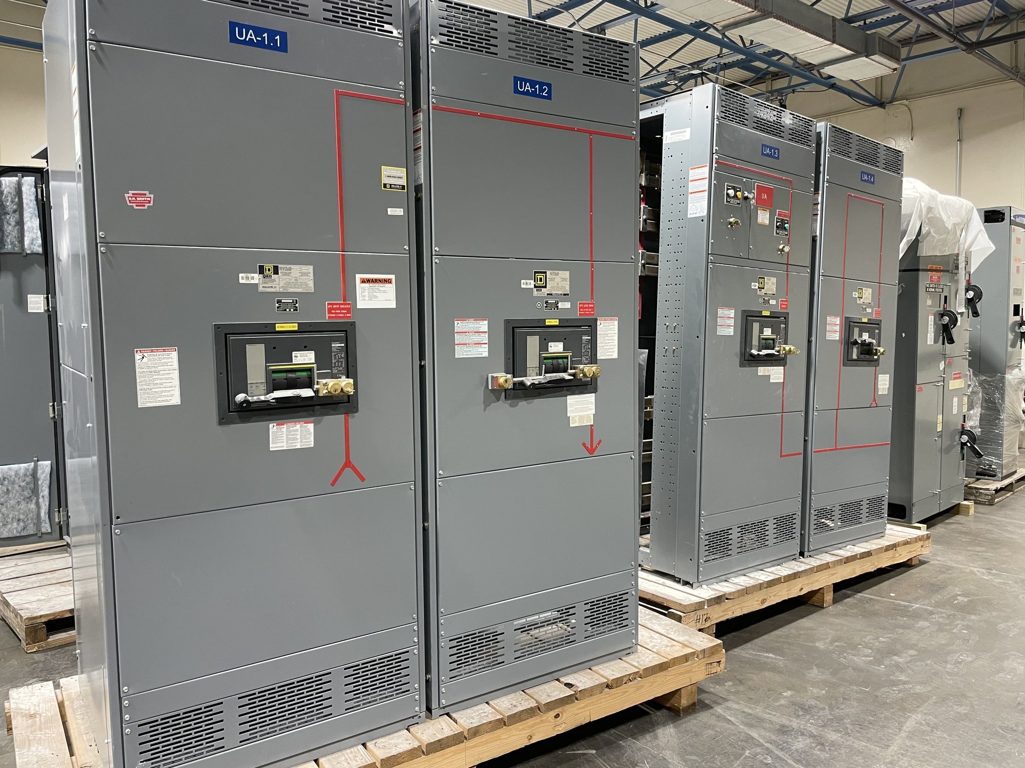
What long-time protection does
Long-time overcurrent protection responds to current above a circuit’s continuous operating range that persists beyond a brief interval. It is intended to address sustained overload conditions, rather than the rapid, high-current events handled by short-time or instantaneous protection. The protective device measures current and applies a time-current characteristic to determine when to trip.
The long-time function is one part of a coordinated protection scheme, not a standalone setting to choose by rule of thumb. Its operation must be considered alongside conductor and equipment capabilities, expected loading, upstream and downstream devices, and the applicable design criteria. The final selection depends on the actual system and requires review by qualified electrical professionals.
Pickup: the current threshold
Long-time pickup is the current level at which the protective function begins its timing response. Depending on the trip unit, the setting may be expressed as an amperage value or as a multiplier of a sensor or rating value. Confirm the device’s adjustment method and available range; do not assume two trip units use the same reference or setting increments.
To establish a useful pickup value, provide the circuit’s intended load, relevant continuous-load assumptions, conductor information, equipment ratings, and the protective device details. A setting that is too low can cause unwanted trips during normal operation or expected load changes. A setting that is too high may not provide the intended protection. Engineering review must reconcile operating needs with the limits of the protected circuit.
Delay: balancing continuity and protection
Long-time delay determines how quickly the device trips after current exceeds pickup. A longer delay can allow temporary overloads or downstream devices time to clear a fault first, helping preserve service to unaffected circuits. But delay is not simply a way to avoid nuisance trips: excessive delay can leave conductors or equipment exposed to damaging current for longer than the design permits.
Trip-unit characteristics may describe delay using time bands or a reference point on a time-current curve. Coordination depends on comparing the full curves over the relevant current range, including tolerances and device behavior—not just comparing the displayed delay settings. Share available manufacturer curves and device data for upstream and downstream protective devices so the engineer can assess selectivity and protection together.
Coordination and system information
A coordination study evaluates how protective devices operate relative to one another under specified fault and overload conditions. Long-time settings may affect whether a feeder device trips before a main device, but coordination outcomes also depend on short-time and instantaneous functions, available fault current, and the characteristics of connected equipment. No single pickup or delay value guarantees coordination across every operating condition.
For a new switchboard quotation, identify the system voltage and configuration, service or feeder role, requested ampere ratings, load schedule, available fault-current information, and any existing coordination criteria. Include the make and model or trip-unit data for devices that must coordinate with the new assembly. If study results or one-line diagrams are available, provide them for review; missing information should be identified rather than replaced with assumptions.
Specify the assembly and handoff
When requesting a manufacturer-built switchboard, distinguish the required assembly characteristics from the settings that the project engineer will determine. State the requested device types, frame or sensor details where known, adjustable trip functions, metering or control requirements, enclosure and connection considerations, and the documents expected with the equipment. UL 891 applies to switchboard assemblies; it does not establish a long-time setting or replace project-specific protection engineering.
For Georgia projects, share the delivery destination, site access constraints, required-on-site date, and any sequencing needs so shipping and order planning can be reviewed for the specific configuration. American-made components and custom-built options may be considered as the design and availability are confirmed. Scope, component availability, and schedule are confirmed for each order; do not treat a general preference as confirmation of a particular part or delivery date.
Prepare a useful request
A focused request should state what the long-time function needs to accomplish, which circuits or devices are involved, what coordination documentation exists, and which decisions remain open for engineering review. Ask whether the proposed trip-unit options provide the required adjustment range and documentation for the project study. Avoid specifying a final pickup or delay without the circuit data and coordination basis needed to support it.
Before submitting specifications for a Georgia order, gather the one-line diagram, load and conductor information, device data, project delivery details, and the engineer’s protection criteria. Identify any unresolved assumptions explicitly. This gives the manufacturer a clearer basis to configure the new switchboard and confirm scope, while the responsible project professionals retain authority over settings, coordination, installation, and commissioning.