Set operating priorities before selecting equipment
Start by classifying loads according to their consequence if interrupted and the time they can tolerate an interruption. Life-safety and legally required loads, where applicable, need to follow the project’s governing design requirements; other critical process, communications, refrigeration or building loads may have different priorities. The responsible engineer should establish the classifications and confirm them with the owner and authority having jurisdiction.
For each load or load group, document its normal and emergency source, approximate demand, starting characteristics, acceptable interruption, and whether it can be shed and restored automatically. A load that is important during an outage may still need to drop temporarily to preserve generator stability. Record the operational reason for each priority so purchasing and controls teams can translate it into a clear sequence.
Define capacity and control logic
Load-shedding logic must reflect the generator’s usable capacity under the specified operating conditions, not just its nameplate kW. The engineering review should consider kW and kVA limits, power factor, ambient and altitude derating where relevant, step-load acceptance, motor starting, nonlinear loads, and any parallel-generator operating modes. Confirm whether the control basis is measured real power, frequency, available capacity, breaker status, or a combination.
Specify what initiates each action, the order in which loads are removed, any delay or persistence before a command, and the conditions for restoring loads. Restoration may need to be staged to avoid a second overload as motors restart or process loads return. Identify manual overrides, alarms, loss-of-sensor behavior, control power requirements, and the response to a failed communications link; these details should be reviewed by the project engineer.
Coordinate the switchboard and interfaces
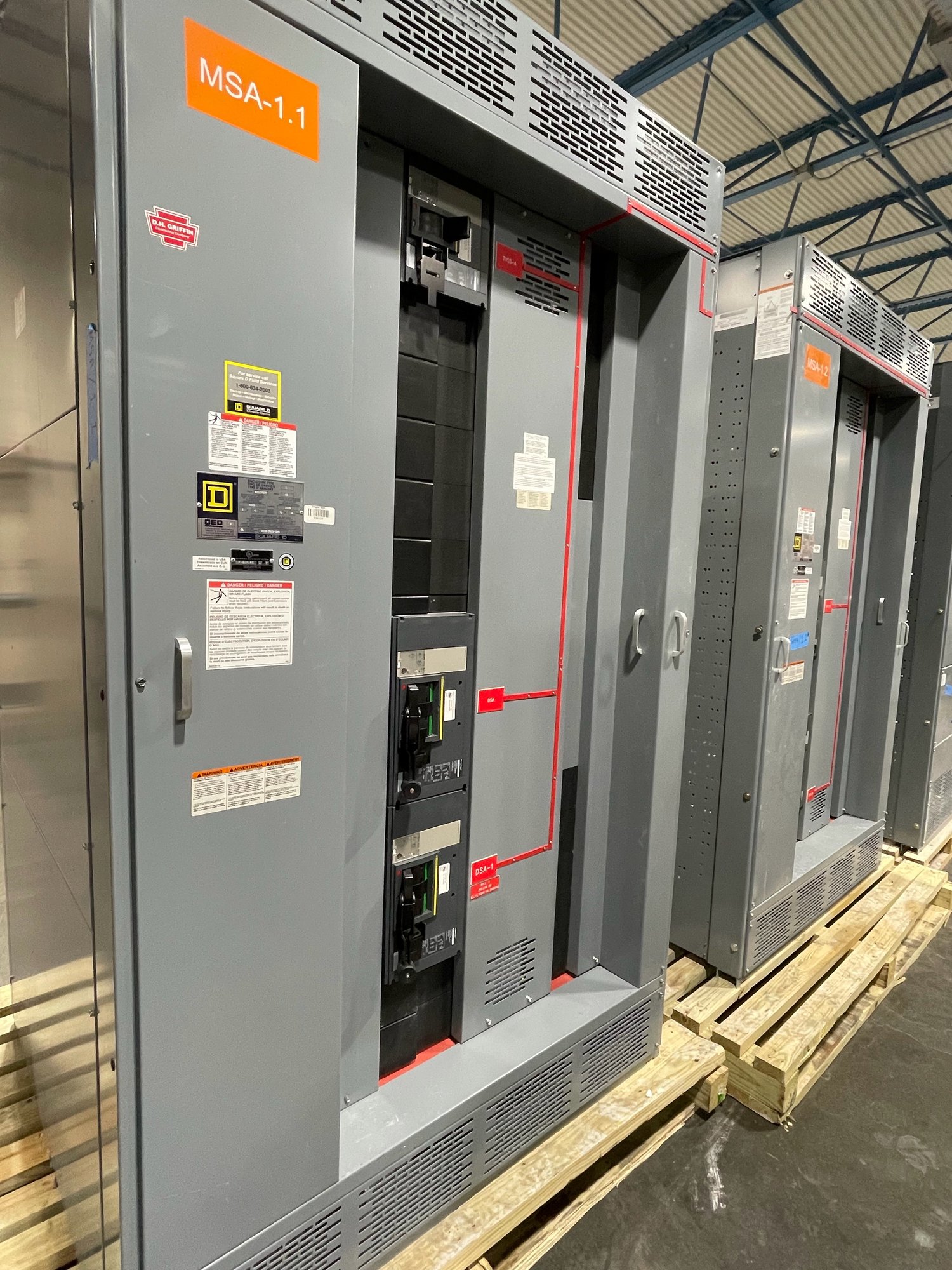
The switchboard arrangement needs to support the intended sequence. Identify the breakers or load groups subject to automatic control, their trip or control method, auxiliary contacts, metering points, and the interface to the generator controller or separate load-management system. Confirm the required control voltage, terminal points, signal types, and responsibility for furnishing and wiring each interface before drawings are released.
For a custom-built assembly, provide a one-line diagram, preliminary load schedule, generator data, source and tie arrangements, and the desired operating modes. UL 891 applies to switchboard assemblies; it is not a blanket listing for medium- or high-voltage switchgear. The design team must establish the applicable equipment scope, ratings, and review requirements for the actual system.
Use verified data, not assumed demand
A useful load schedule distinguishes connected load from expected operating demand and identifies loads that can start together. Include motor horsepower and starting method, transformer inrush concerns, UPS or rectifier behavior, variable-frequency drives, and any large cyclic or process loads. State which values are measured, calculated, estimated, or still pending so the engineer can assess uncertainty before setting thresholds.
Ask whether the proposed shedding blocks preserve essential functions, whether a single breaker trip removes more load than intended, and whether generator capacity changes with operating mode. If multiple generators can run in parallel, define how the controls allocate reserve and respond to a unit trip. These questions help prevent a sequence that looks adequate on paper but cannot maintain the required loads in an actual transition.
Verify the sequence and hand off clearly
Commissioning should verify the sequence against approved settings and the final load schedule. The test plan can address source transfer, generator loading, staged shedding, alarms, override operation, restoration delays, and abnormal conditions such as a failed input or unavailable generator. Establish safe test methods and acceptance criteria with the engineer, generator-control provider, switchboard supplier, contractor, and facility representative.
At turnover, provide the approved sequence of operation, breaker and I/O mapping, final settings, test records, and clear procedures for changing priorities or thresholds. Explain which party owns each control adjustment and what engineering review is required before a change. This record helps facilities staff troubleshoot behavior without treating an undocumented field adjustment as an approved design change.
Prepare a project-specific quote request
For a manufacturer quote, share the one-line, load schedule, generator and controller information, desired shedding and restoration order, operating modes, interface responsibilities, and required switchboard scope. Include project location in Georgia, drawing and submittal milestones, target delivery window, and any site access or receiving constraints. Exact configuration, component availability, and schedule are confirmed for each order.
Before release, have the project engineer confirm the load priorities, capacity assumptions, control sequence, ratings, and applicable authority requirements. Then align the approved drawings and test plan with procurement and installation responsibilities. This gives the manufacturer a defined basis for a custom switchboard assembly and gives the project team a practical path from specification through verification and handoff.