What the instantaneous element does
An instantaneous overcurrent element commands a circuit breaker to trip when current exceeds its pickup threshold, without an intentional time delay. It is one part of a protective device’s trip function; the breaker still has a physical interruption time. The element is generally intended to respond to high-current faults, while other protection functions address lower overloads or fault currents with time delays.
A lower pickup can detect some faults at lower current, but it may also respond to faults beyond the protected feeder, depending on system conditions and device characteristics. A higher pickup may reduce that overlap, yet could leave a high-current fault to another protective function. The appropriate setting depends on the complete system, not on a generic setting that can be applied across switchgear projects.
Pickup, tolerance, and actual clearing
Specify the trip unit and breaker model, available adjustment range, pickup units, and how the setting is represented, such as a multiple of sensor rating or a current value. Confirm the trip unit’s published tolerances and operating behavior, including any short-time function, override, or other feature that can affect response. A dial value alone does not establish an exact trip current or total fault-clearing time.
Coordination studies should use the applicable time-current curves and device data, including the breaker’s opening and interruption characteristics. Compare the full range of expected fault current at the device with the protection curve, rather than checking only a nominal value. The study should also consider the equipment’s interrupting rating and withstand limits; protection settings do not increase those ratings.
Selective coordination tradeoffs
Selective coordination aims to have the protective device closest to a fault operate while upstream devices remain closed when practical. An upstream instantaneous element may trip for a downstream fault if its pickup is reached before the downstream device clears. Raising or disabling an instantaneous function can sometimes improve selectivity, but it is not an automatic solution and may affect clearing time or protection objectives.
Review device curves and manufacturer coordination information for the actual combinations proposed. Consider faults at multiple locations, normal operating configurations, and any alternate source or tie arrangement that changes fault current. Where the study identifies a conflict, the engineer can assess available settings or device options and document the resulting coordination limits. Do not assume that devices from different manufacturers, or different trip-unit versions, coordinate based on frame size alone.
System data the study needs
Useful inputs include the one-line diagram, source and transformer data, conductor lengths and sizes, grounding method, motor contribution, and the operating configurations that affect available fault current. Identify the specific upstream and downstream protective devices, their trip-unit and sensor details, existing settings, and any required coordination or clearing-time criteria. If a study is underway, share its assumptions and the latest device schedules so the switchgear design can be checked against them.
Georgia facilities may have utility-fed, generator-backed, or interconnected operating arrangements; the design team should provide the fault-current information for each relevant source condition. Utility data and study assumptions should be confirmed by the responsible project professionals. If values remain preliminary, identify them clearly so equipment selection and setting decisions are not treated as final before the system analysis is complete.
Specification and procurement handoff
For a quote, share the required switchboard or switchgear scope, system voltage and configuration, breaker frame and trip-unit requirements if established, available fault-current data, and the intended coordination approach. Include the latest one-line, equipment schedule, drawings, and project delivery location in Georgia. State which settings are preliminary, who will furnish the final study, and what documentation is expected with the order.
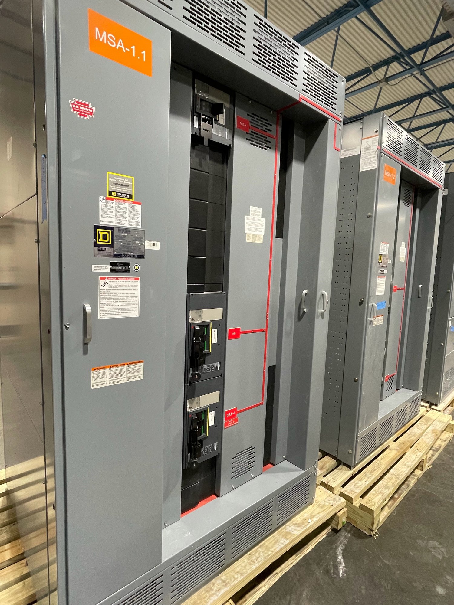
We build and supply new switchgear and UL 891 switchboard assemblies, with custom configurations and American-made components available as applicable to the specified scope. UL 891 applies to switchboards, not as a blanket listing for medium- or high-voltage switchgear. We review requirements and confirm scope, component availability, schedule, and shipping arrangements for each order; Georgia delivery planning should align with site access, receiving, and installation sequencing.
Close the setting loop
Before release, have the responsible engineer reconcile the final instantaneous pickup with the completed coordination and fault-current studies, device data, and project requirements. Record the approved setting, its basis, and any operating configuration assumptions in the project documentation. If a study revision changes fault current or device selection, recheck the setting rather than carrying forward an earlier value by default.
Send the current one-line diagram, device schedule, fault-current inputs, and coordination criteria with the quote request, and identify any unresolved study items. That gives the equipment team a defined basis to review the proposed configuration and helps the project team plan Georgia delivery around the approved design and site schedule.