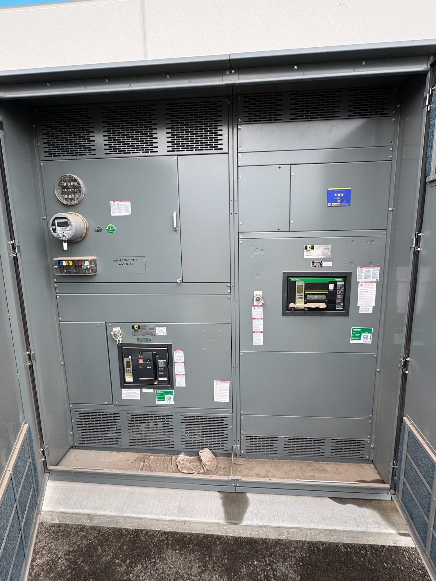
Equipment protection, not personnel protection
Equipment ground-fault protection (GFPE) detects current returning outside the normal circuit path and can initiate an alarm or trip, depending on the design. It is intended to help protect conductors and equipment from damaging ground faults. Its function is distinct from personnel-protection devices designed to reduce shock hazards, and it does not replace grounding, bonding, overcurrent protection or safe work practices.
A ground-fault event may involve current too low to operate a conventional phase overcurrent device promptly, while still creating damaging heat. The protection method may use current sensors and a relay or a trip unit with ground-fault functionality. The appropriate arrangement depends on the system grounding method, source and distribution configuration, equipment type, and project requirements; no single setting or device fits every installation.
Establish where protection applies
Start by identifying the applicable electrical code edition, adopted local requirements, system voltage and service arrangement. Requirements can depend on factors such as the service or feeder location, system configuration, and equipment characteristics. The project engineer and authority having jurisdiction should determine applicability for the specific installation rather than assuming that a requirement applies to every switchboard or panel.
Document the one-line diagram, service and feeder boundaries, grounding method, available fault-current information, and downstream equipment. Note any alternate sources, ties, generators or other operating modes that change current paths. For a Georgia project, confirm the governing requirements with the design team and relevant authority for the project location. Manufacturer scope should follow the reviewed design, not substitute for it.
Define sensing, trip and alarm functions
The specification should identify which breakers or sections require ground-fault functionality and whether the intended response is alarm, trip, or both. It should also state the sensing approach where known, the desired trip unit features, and any required status indication or remote signal. Clarify whether protection is needed at a service, feeder, or other point, and how the function relates to upstream and downstream protective devices.
Trip behavior depends on the selected pickup and time delay, as well as the sensing arrangement and system conditions. A ground-fault sensor may monitor phase conductors and, where applicable, the neutral; sensor placement and wiring must suit the grounding and circuit arrangement. Ask the engineer to define the intended operating logic and confirm that the selected equipment can implement it. Do not infer a setting from a general equipment description or a nominal rating alone.
Coordinate settings with the system
Settings should be selected through an engineering review of the system study, equipment limits, and protective-device coordination. The review considers expected ground-fault current, clearing time, conductor and equipment withstand, and the need to coordinate with upstream protection. A setting that is too high or delayed may not provide the intended protection; one that is too low or fast may cause unwanted trips or disrupt selectivity.
Share available short-circuit and coordination studies, proposed settings, and any project-specific trip-unit requirements with the switchgear manufacturer during specification. If studies are incomplete, identify who will provide them and when settings will be finalized. Settings, sensor ratios, and trip-unit capabilities must be checked against the actual system and selected equipment. Engineering review and applicable authority review remain necessary before final approval, installation, or energization.
Prepare the switchgear scope and quote
For a new switchboard quotation, provide the one-line diagram, equipment schedule, voltage and ampacity, service or feeder designation, system grounding details, and the required ground-fault functions. Include known study results, trip-unit and communication requirements, alarm points, enclosure and installation constraints, and the project schedule. State which details are preliminary so the configuration can be reviewed without treating assumptions as approved design decisions.
Also identify the delivery location in Georgia, receiving constraints, requested ship window, and any sequencing needs for a phased installation. We build new equipment to the confirmed project scope, with American-made components, custom configurations and nationwide shipping; exact component availability, configuration and timeline are confirmed for each order. UL 891 applies to switchboard assemblies, not as a blanket listing for medium- or high-voltage switchgear, so specify the equipment type and applicable requirements precisely.
Close the design-to-delivery handoff
Before release, reconcile the approved one-line, equipment schedule, ground-fault function, and setting responsibility. Confirm which values are design settings and which are final field adjustments, and identify the party responsible for testing and commissioning under the project plan. Keep revision control clear if studies or settings change after the equipment configuration has been reviewed; changes can affect the selected devices and scope.
For a Georgia project, send the current drawings, study status, required protection behavior, and delivery constraints with the quote request. Ask for confirmation of the proposed equipment scope, unresolved design inputs, and the order-specific schedule before procurement. This gives the engineering team and manufacturer a defined basis to resolve ground-fault questions before build and helps the project team plan delivery and commissioning around the approved design.