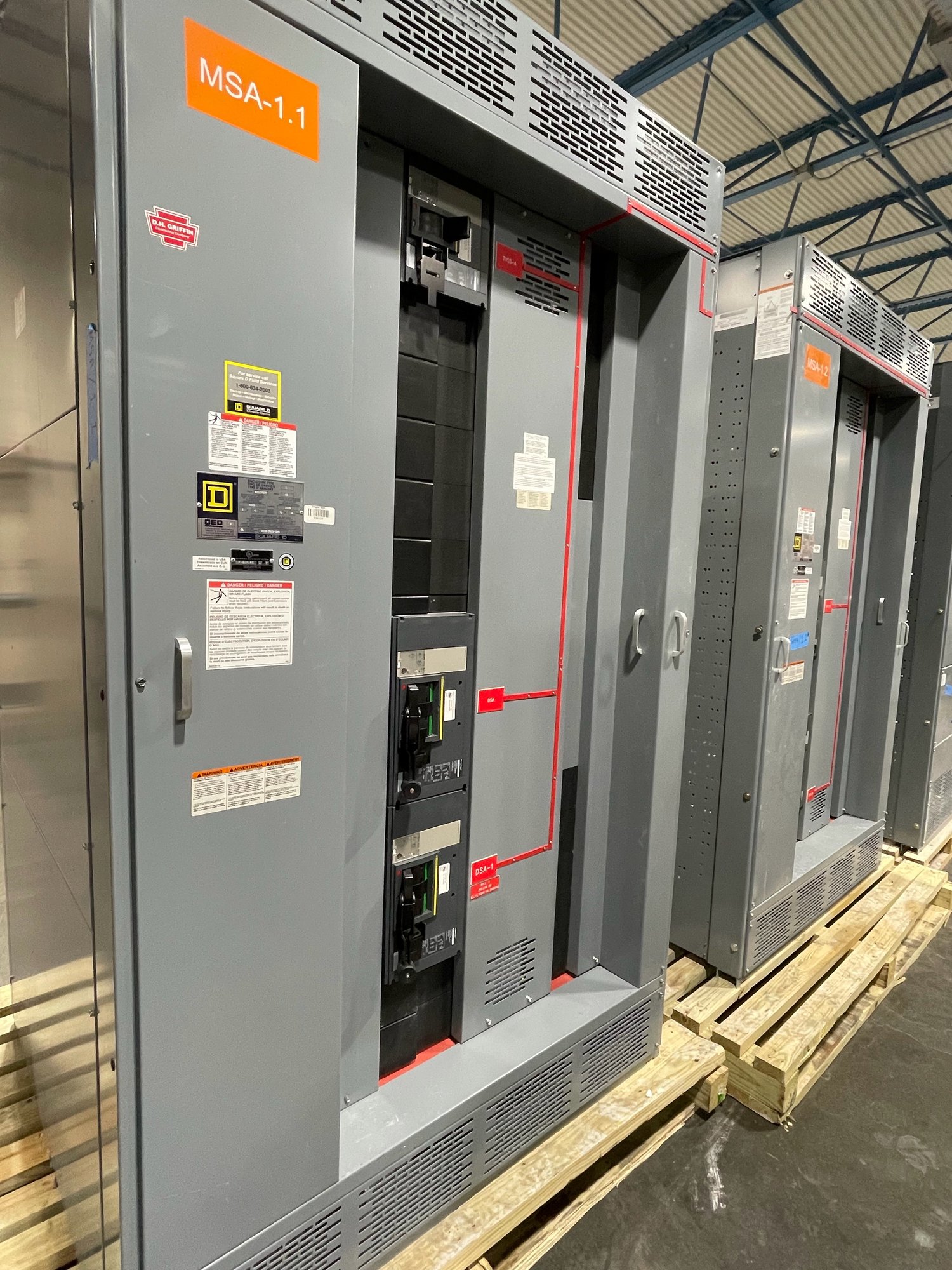
Define the switching function first
High-voltage equipment is selected for a specific position and duty in a power system, not simply by choosing a voltage class. A project may require circuit breakers, disconnect switches, grounding switches, instrument transformers, bus, protective relays, or an integrated arrangement. The one-line diagram should show how each device fits the source, transformer, feeder, and load configuration, including normal and alternate operating paths.
Clarify what the equipment must accomplish: interrupt load or fault current, isolate a circuit, provide visible isolation where specified, ground conductors for maintenance, or support a substation expansion. Identify indoor or outdoor installation, the number of circuits, bus arrangement, control-voltage requirements, and intended operating sequence. These details establish the scope and prevent a quotation from assuming functions that the project does not need.
Match ratings to the system study
Request ratings that correspond to the project’s system conditions and engineering studies. Key values can include maximum system voltage, basic insulation level, power-frequency withstand, continuous current, short-circuit interrupting capability, short-time withstand, and momentary or peak withstand. The applicable values depend on the system, equipment type, installation conditions, and governing specifications; a nominal voltage alone does not define an adequate assembly.
Ask the engineer of record or utility to identify the required standards and acceptance criteria for each device. Confirm frequency, grounding arrangement, altitude, ambient temperature, pollution or contamination exposure, seismic criteria where applicable, and any specified switching duty. For outdoor equipment, environmental and enclosure requirements matter; for indoor applications, room clearances, cable entry, ventilation, and access can constrain the design. Ratings and final suitability require project engineering review and approval by the relevant authority.
Verify manufacturer capability and scope
Evaluate a manufacturer against the equipment actually being specified. Ask which high-voltage product types and voltage ranges it designs or builds, what manufacturing and quality controls apply, and what routine, design, or type-test evidence is available for the proposed configuration. Request the applicable standards, test documentation, drawings, and exceptions list for review. Do not treat a general switchgear capability statement or a UL 891 reference as proof of qualification for high-voltage equipment; UL 891 applies to switchboard assemblies, not as a blanket listing for medium- or high-voltage switchgear.
Establish whether the manufacturer is responsible for the complete assembly or only named components, and identify any engineering, protection, controls, testing, installation, or commissioning work outside its scope. Confirm who provides relay settings, wiring interfaces, control schematics, operating instructions, and field support if required. Manufacturer qualifications should align with the project’s technical specification and procurement rules, rather than rely on assumptions about certification or prior installations.
Resolve interfaces before release
High-voltage equipment connects to systems and structures that may be specified by separate teams. Share transformer data, cable type and termination details, bus connections, grounding requirements, control and communications interfaces, and available space. Check the physical layout against foundations, conduit routes, phase spacing, cable pull access, maintenance clearances, and the sequence for future additions. A dimensional drawing review can expose conflicts before fabrication and help coordinate civil, electrical, protection, and construction documents.
Document operating and interlocking requirements, including local and remote control, indication, alarms, trip and close circuits, and any restrictions on switching sequences. Identify required interface points and responsibility for wiring between equipment sections or to site systems. Agree on drawing submittals, review milestones, approved deviations, inspection or test documentation, and the information needed for turnover. Clear ownership of these items reduces late design changes and leaves the installation team with usable records.
Plan procurement and Georgia delivery
For a useful quotation, provide the latest one-line diagram, equipment schedule, technical specification, system-study ratings, site conditions, required standards, control schematics if available, and delivery destination in Georgia. Include the requested scope, options, quantity, drawing and documentation requirements, inspection expectations, and target project milestones. State what remains under the engineer’s direction or another supplier’s scope. The manufacturer can then identify open technical questions, confirm configuration and availability, and provide a project-specific schedule; lead time and final scope are confirmed for each order.
Coordinate shipping around site readiness rather than treating delivery as the end of procurement. Confirm receiving access, unloading responsibilities, storage conditions, packaging and handling requirements, and any restrictions on delivery windows. Review the approved drawings and shipment documentation before dispatch, and coordinate installation and energization planning with qualified personnel and the responsible utility or authority. For the next step, send the project’s one-line diagram, required ratings, equipment scope, and Georgia delivery location so the proposed configuration and schedule can be evaluated against the actual application.