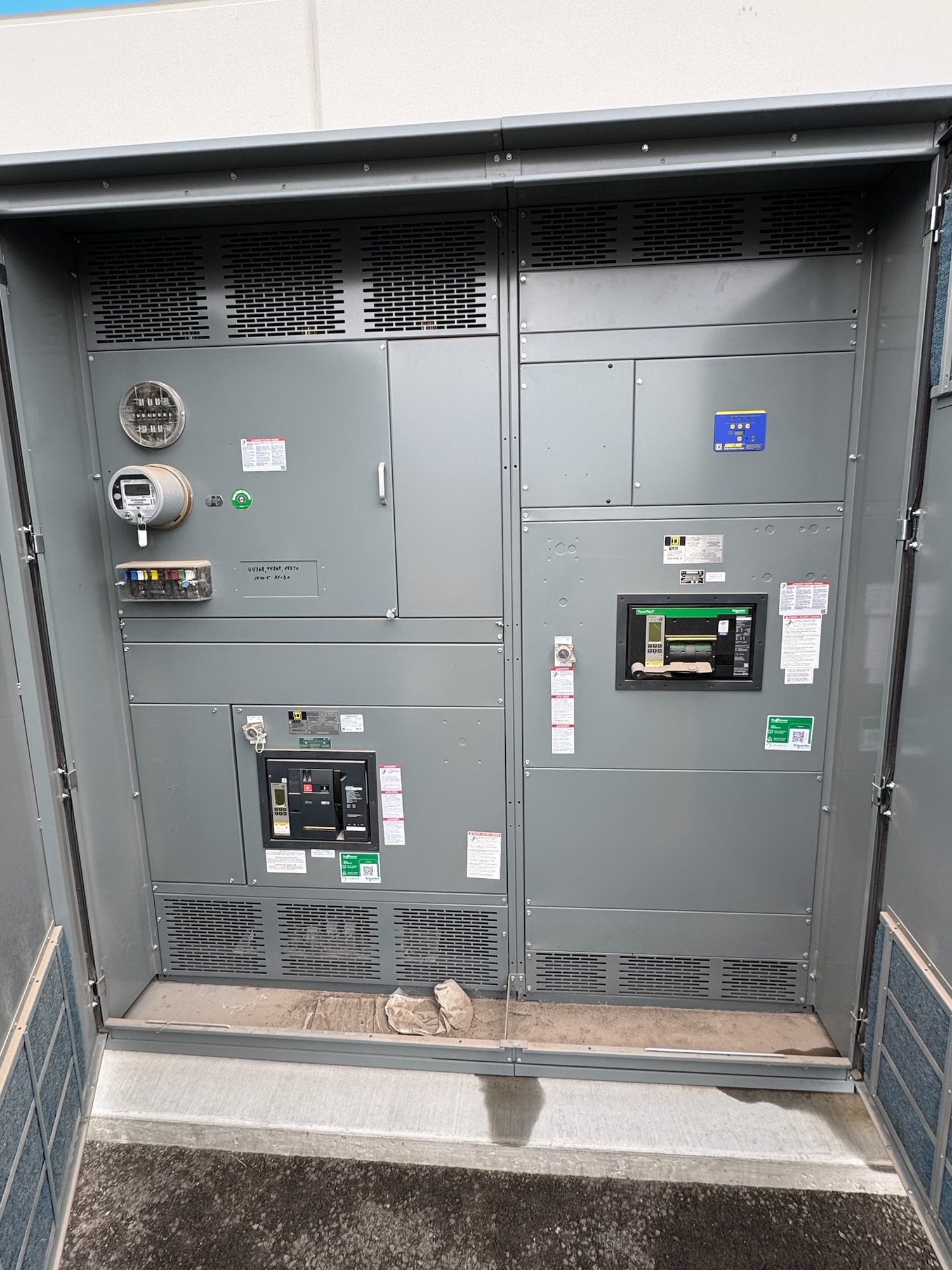
Plan the distribution path
A switchboard receives power at its service or supply section and distributes it through buses and outgoing circuits to downstream equipment. Its arrangement depends on the source, the number and type of loads, and how the facility needs to isolate or protect each branch. A one-line diagram is the clearest starting point for showing incoming conductors, mains, feeders, tie connections and load destinations.
Define the electrical service and operating arrangement before choosing section dimensions. Share the system voltage and phase, available fault-current information, grounding method, source details, and whether the design includes one source or multiple sources. Identify expected feeder quantities and destinations as well as space for future circuits. These details help the engineering team develop a configuration that fits the intended distribution path rather than relying on assumptions.
Understand the assembly
A switchboard is typically built from connected metal-enclosed sections. Depending on the design, sections may house the incoming service, main disconnect or protective device, distribution buses, feeder devices, metering, and control components. Bus arrangement and section layout affect how power moves through the assembly, where conductors enter and leave, and how workers access devices for operation and maintenance.
The enclosure and cable space must suit the installation, not just the device count. Confirm indoor or outdoor application, mounting method, conductor entry and exit direction, available room, and access clearances with the project design team. Include site constraints such as doorways, equipment routes and the intended lineup location. Final dimensions and construction depend on the selected components, conductor requirements, drawings and applicable review.
Select devices around the loads
Main and feeder devices should reflect the circuit duties they serve. The engineer’s design determines the required device type, ampere rating, trip functions, interrupting capability and coordination approach. Molded-case circuit breakers, insulated-case devices, fusible switches or other options may be considered where appropriate to the design and assembly. Do not select a device solely by matching a load’s nominal current; fault-current conditions and protection objectives matter too.
For a useful quote, provide the one-line diagram and available protective-device schedule, including specified manufacturer or product constraints if applicable. Identify any metering, surge protection, ground-fault functions, shunt trips, auxiliary contacts or remote indications called for by the design. The final device selection and ratings require engineering review against system data and project requirements. Share known operating, maintenance and coordination needs early so they can be evaluated with the configuration.
Apply UL 891 to the right scope
UL 891 is a standard for switchboards. It applies to switchboard assemblies within its scope; it is not a blanket listing for every piece of equipment described as switchgear, nor does it establish that every component or project condition is covered. When UL 891 is required, specify that requirement for the applicable assembly and confirm the offered construction and documentation match the project’s requested scope.
Do not treat a standard reference as a substitute for reviewing the complete design. The engineer and authority having jurisdiction determine applicable requirements for the installation, including how the assembly interfaces with the service, conductors, protection and surrounding equipment. Share the project specification and any required submittal expectations with the quote request. The proposed scope, ratings, availability and schedule are confirmed for each order.
Prepare a complete quote package
A focused request includes the latest one-line diagram, load or feeder schedule, project specification, required ratings, and any available fault-current and coordination information. Add the requested section arrangement, enclosure conditions, cable entry preferences, metering and control requirements, and the desired drawing or submittal milestones. Identify open design decisions instead of leaving them implicit; clear questions help separate confirmed requirements from items that still need engineering direction.
Procurement teams should also state the delivery destination in Georgia, required receiving window, site access constraints and any coordination needed for unloading or equipment routing. Georgia delivery can be planned as part of the order, with shipping method and timing confirmed against the final configuration and schedule. New equipment is built to the agreed scope; exact component availability and production timing are confirmed for each order rather than assumed from a general estimate.
Close the design and handoff
Before release, reconcile the approved drawings with the one-line diagram, device schedule, section lineup, conductor entry, and project specification. Confirm that ratings, device functions, accessories, metering and control interfaces are documented. Resolve changes through the project’s engineering and procurement process so the manufacturing scope, installation plans and submittals stay aligned. Any design or rating remains subject to engineering review and authority approval for the specific installation.
For a new Georgia project, send the current drawings and specification together with the site delivery requirements, then identify the decisions that remain open. Ask for confirmation of the proposed assembly scope, device configuration, applicable UL 891 documentation, and order-specific availability and timing. This gives the project team a practical basis to complete review and coordinate the switchboard with the service, feeders and installation plan.