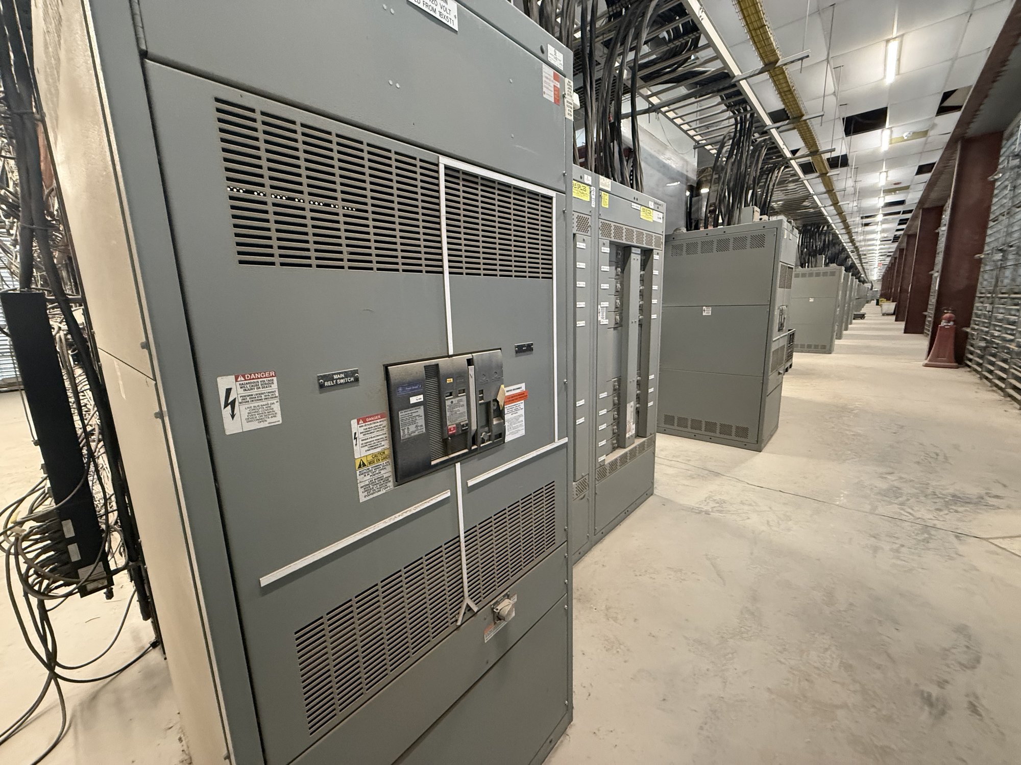
Start with the facility’s power sequence
For a healthcare project, describe what the normal and alternate power sources are expected to do, and how the facility intends to transfer between them. Share the one-line diagram, source and load information, generator or other backup-source interfaces, transfer equipment arrangement, and any planned future additions. These details help establish the switchgear boundaries and identify coordination points without assuming a particular hospital topology or operating sequence.
Clarify which loads the project is intended to serve and how the facility’s engineering team has classified or grouped them. Switchgear selection depends on the actual system design, not simply on the building’s healthcare use. The consulting engineer and facility representatives should define required operating modes, protection and coordination criteria, and applicable review requirements; the equipment scope can then be evaluated against those documents.
Define backup-source interfaces early
Backup integration involves more than providing a connection point. Confirm the expected incoming sources, switching arrangement, control and indication needs, interlocks, metering, and interfaces to any transfer equipment. Identify who supplies and configures each device, how control wiring and communications are divided, and which party will verify the sequence during startup. Clear responsibility boundaries reduce the chance of gaps between switchgear, generator, transfer, and building-system packages.
For each source, provide the engineer-approved electrical data and operating assumptions available for the project. These may include system voltage, phase, frequency, grounding approach, fault-current information, and protective-device requirements. Do not select interrupting or withstand ratings from general healthcare guidance; the project engineer must establish suitable values and the authority having jurisdiction must review applicable requirements. Final configuration and ratings depend on verified project documents.
Make maintenance access part of the layout
A maintainable lineup needs room for the work it is expected to support. Share the proposed electrical-room plan, equipment locations, door and corridor dimensions, access routes, adjacent equipment, and any overhead or below-floor constraints. Note whether technicians need front access only or access at other faces, and identify the anticipated cable entry and exit directions. The equipment arrangement should be reviewed against the actual room and installation plan rather than chosen from a nominal footprint alone.
Discuss how the facility expects to isolate equipment for inspection or service and what operating constraints apply while portions of the system are unavailable. Those decisions belong with the facility’s electrical and operations teams and the project engineer. They affect lineup divisions, device arrangement, access clearances, and coordination with the backup-power plan. Do not rely on an assumed maintenance method or clearance; confirm the design and applicable requirements before release for manufacture.
Resolve scope, documentation and procurement
A useful quote request includes the latest one-line diagram, specifications, load and source data, room drawings, cable termination requirements, preferred equipment arrangement, and the project schedule milestones. Identify required metering, protective devices, control components, communications interfaces, and any owner-furnished equipment. Also state whether the request covers switchgear, a UL 891 switchboard assembly, or defined portions of a broader distribution package. UL 891 applies to switchboards; it is not a blanket listing for medium- or high-voltage switchgear.
Ask which submittals, drawings, test records, and interface details are included in the proposed scope, and flag document review dates that drive the project. Our team can evaluate a custom configuration using the information provided and confirm the applicable equipment scope, availability, and timeline for that order. Any certification or listing claim must be tied to the specific assembly and confirmed documentation; do not infer it from a component or from a different equipment category.
Coordinate delivery and project handoff in Dunwoody
For a Dunwoody job, provide the delivery address, site access limits, receiving hours, unloading arrangements, staging area, and any restrictions on truck or equipment movement. Georgia delivery can be planned around the project’s receiving and installation sequence, but service coverage, shipping arrangements, and timing are verified individually. Confirm who receives the equipment, checks it for transit issues, stores it under the required conditions, and releases it to the installation team.
Before the order is finalized, align the approved submittals, manufacturing scope, delivery plan, and field responsibilities among the owner, engineer, contractor, and relevant equipment suppliers. Share changes to source data, room layout, schedule, or interface ownership promptly for review; a change can affect configuration and timing. Have qualified electrical personnel handle installation, testing, and energization under the project’s approved procedures and required reviews. Start your quote request with the one-line diagram, room plan, backup-source details, and Dunwoody delivery constraints so the scope can be checked against the real project.