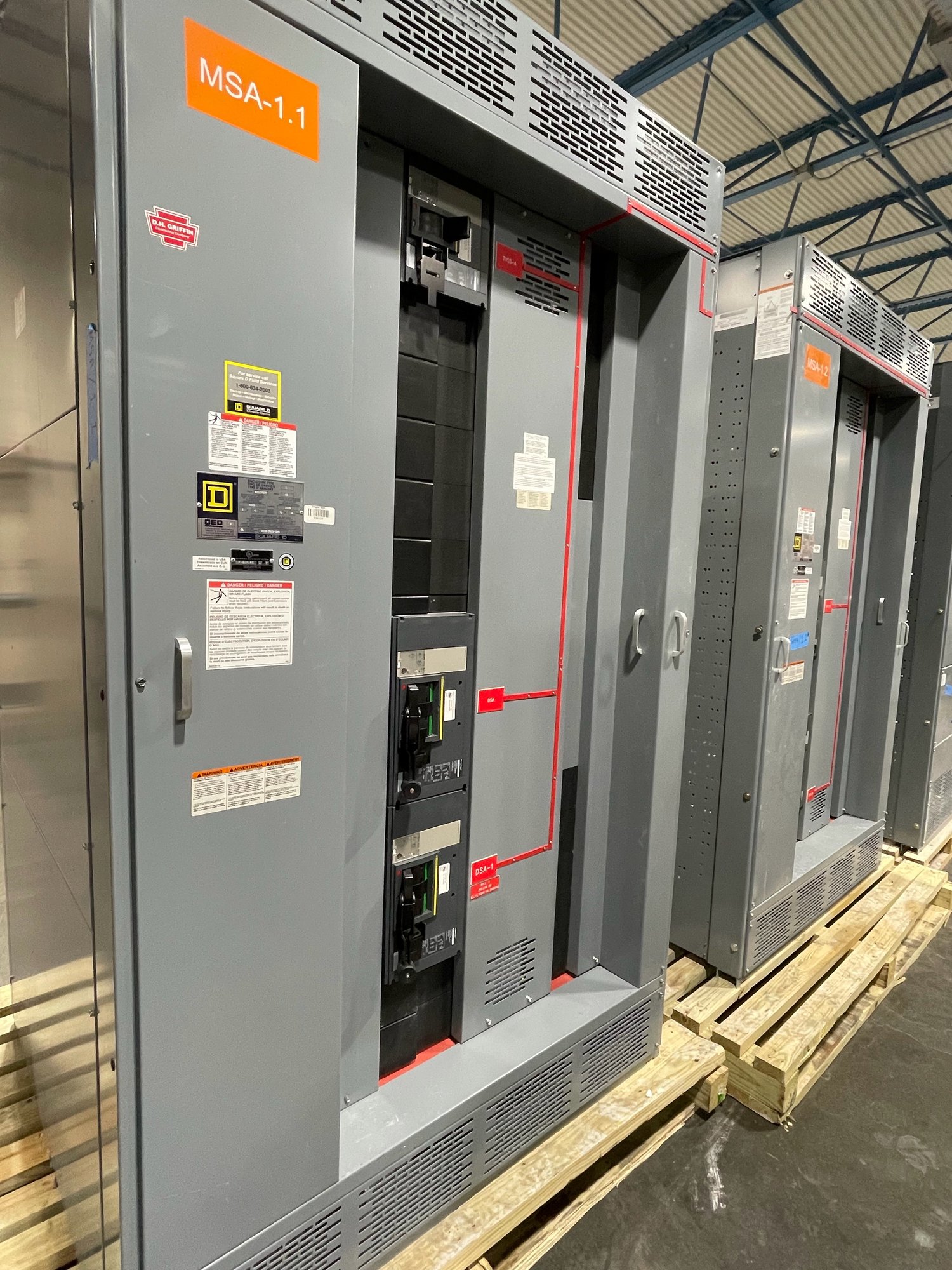
Define the elevator power path
Start with the electrical one-line and identify where elevator loads connect to the building distribution system. The project may require a dedicated feeder for each elevator, a shared feeder arrangement, or separate distribution for different elevator groups. The design team should state the intended topology, source voltage and phase, system grounding, available fault-current information, and the location of the elevator equipment served. These details establish the basis for switchgear configuration without assuming a particular building layout.
Separate elevator loads from other building loads where the design and applicable requirements call for it. Identify controller, machinery, cab, sump pump, ventilation, and auxiliary loads as applicable, and clarify which are supplied through the elevator distribution. Confirm motor and controller data, including starting characteristics and manufacturer requirements, rather than sizing from general elevator descriptions. A clear load schedule helps engineering evaluate feeder and protective-device choices and helps purchasing compare quotations on a consistent scope.
Coordinate feeder protection and disconnects
Elevator disconnecting means and upstream protective devices must work together as part of the complete installation. The electrical engineer, elevator contractor, and equipment suppliers should identify disconnect locations, device types, ratings, accessory requirements, and any shunt-trip or monitoring interfaces required by the design. Confirm whether disconnects are furnished in the elevator equipment, in a separate enclosure, or as part of the distribution assembly; avoid counting the same function twice or leaving it out of every package.
Coordination depends on the actual elevator controller, feeder conductors, fault-current conditions, and protective-device characteristics. Gather the elevator manufacturer's published requirements and the engineer's coordination criteria before finalizing switchgear details. Where selective coordination, ground-fault protection, emergency operation, or remote indication is specified, document the applicable circuits and functions. We can build the switchgear scope around the approved requirements, while the responsible design professionals determine device selection and verify the complete system.
Plan standby operation deliberately
If elevators are intended to operate from a standby generator or other alternate source, define exactly what transfers and under what conditions. The project documents should identify which elevators receive standby power, whether operation is sequential or simultaneous, how transfer equipment interfaces with the elevator controllers, and what load-management or priority scheme applies. Generator capacity, motor starting, transfer behavior, and other emergency loads can constrain the arrangement, so standby provisions should be coordinated across electrical, elevator, and generator design packages.
Clarify whether the switchgear scope includes source selection, generator connection provisions, control wiring interfaces, status contacts, or only the distribution equipment downstream of transfer devices. Identify normal and alternate sources, required operating modes, and any signals exchanged among systems. Do not assume that an elevator will run during an outage simply because a generator is present. The engineered sequence, installed transfer equipment, elevator controls, and approved operating strategy together determine the result.
Resolve code and design review points
Elevator power requirements depend on project conditions and adopted codes, including the applicable electrical and elevator provisions, local amendments, and authority interpretations. Review the project jurisdiction and permitting basis rather than applying a general rule without context. The engineer of record and authority having jurisdiction should resolve questions about feeder separation, disconnect placement, emergency or standby service, fire-alarm interfaces, and required labeling. UL 891 applies to switchboard assemblies; it does not by itself establish compliance for every elevator system or other equipment in the installation.
Provide the latest one-line, panel or load schedules, elevator equipment submittals, sequence of operation, fault-current data, and any written review comments when requesting a project-specific configuration. Flag unresolved design decisions explicitly so they can be assigned to the appropriate engineer or supplier before release. Equipment ratings, features, and final arrangement must follow the approved design and applicable review; they should not be inferred from a preliminary layout or a general description of the building.
Prepare a quote and project handoff
For a useful quotation, share the project location in Georgia, requested quantity, service characteristics, one-line diagram, load and feeder schedules, elevator controller requirements, standby-power sequence, and specified enclosure or installation constraints. Include required accessories, metering, communications, spare provisions, documentation, and submittal milestones. State which items are furnished by others and identify the intended scope boundary between switchgear, transfer equipment, elevator controls, and field wiring. These answers help define a buildable package and expose gaps while design choices can still be coordinated.
After the configuration is approved, confirm the submittal path, release information, delivery destination, receiving access, and site schedule. We manufacture new switchgear in the United States, use American-made components as specified, and ship nationwide, including to Georgia. Exact component availability, configuration, and production and delivery timing are confirmed for each order. Before procurement release, align the final equipment documents with the elevator contractor and electrical installer so feeder terminations, disconnect interfaces, standby controls, and installation responsibilities are understood.