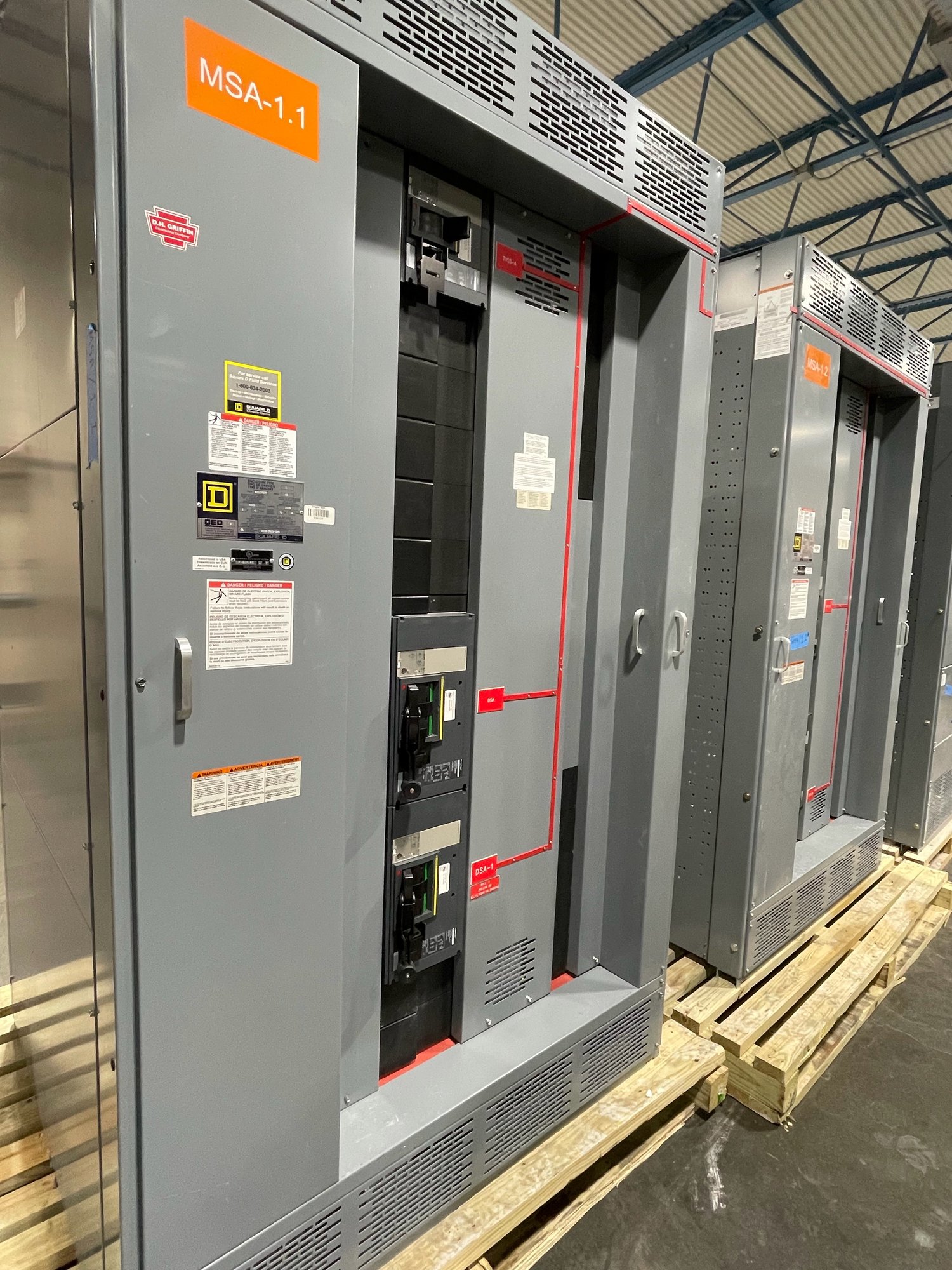
Start with the treatment sequence
Map the loads to the treatment process before defining a switchboard lineup. Intake and transfer pumps, chemical feed systems, mixers, filtration equipment, disinfection systems, clearwell pumps and distribution boosters may have different operating schedules and consequences when unavailable. Identify which loads must remain energized, which can be shed, and which can restart only after an operator or control system permits it.
A process narrative or load schedule helps translate those priorities into equipment requirements. Note normal and alternate operating modes, including seasonal demand or maintenance configurations, and identify any loads shared across treatment trains. The electrical design team should determine how distribution sections, feeders and control interfaces support the intended sequence; the switchboard manufacturer can build to the approved project documents and defined scope.
Account for pump operation and starting
Pump nameplate data and control methods shape feeder selection and lineup planning. For each motor, provide voltage, full-load current, horsepower, starter or drive type, overload and short-circuit information specified by the engineer, and whether operation is continuous, intermittent or standby. Also identify the number of pumps expected to run together and any duty/standby arrangement. These details help prevent assumptions about coincident load or starting conditions.
Variable-frequency drives, soft starters and across-the-line starters impose different electrical and physical requirements. Drives can affect heat dissipation, harmonic considerations, feeder arrangements and enclosure space; the project engineer should establish applicable design criteria. Confirm whether drives are included in the switchboard scope or supplied separately, and clarify required bypass arrangements, isolation, control wiring and maintenance access before procurement documents are finalized.
Keep monitoring and control visible
Treatment continuity relies on more than power reaching motors. Operators may need status, alarm and metering information for incoming sources, bus sections, feeders, pump circuits and transfer equipment. Define the points required by the plant control system, the communication protocol and the responsible party for interface design. Identify whether the switchboard scope includes meters, protective relays, communications hardware, terminal blocks or only provisions for equipment supplied by others.
Coordinate control power and wiring boundaries early. A clear interface schedule can identify signal type, source and destination, while the approved drawings can show where interconnections terminate. Clarify how local controls relate to supervisory control, what indications must remain available during an abnormal source condition, and who supplies and tests external cables. Do not assume compatibility from a general request for remote monitoring; specify the intended devices and interface requirements.
Plan backup sources around operating priorities
Backup power may come from an onsite generator, a second utility source, or another project-defined arrangement. The electrical engineer should establish source capacity, transfer method, fault-current conditions, grounding, protective coordination and the loads permitted on backup. For a water plant, distinguish essential treatment and distribution loads from loads that can wait, and consider whether sequential pump restart is needed to limit demand after transfer.
Provide the intended normal and emergency one-line diagrams, transfer equipment boundaries, generator or alternate-source data, and any load-shed or restart sequence available for review. Confirm whether transfer equipment is part of the switchboard package or furnished separately. UL 891 applies to switchboard assemblies; it does not serve as a blanket listing for medium- or high-voltage equipment. Define voltage class and applicable standards for each part of the project, with engineering and authority review determining suitability.
Resolve site and procurement constraints
For a Georgia project, delivery planning should follow the actual site and construction sequence, not an assumed local inventory or fixed schedule. Share the delivery address, required on-site date, receiving hours, unloading capability, access limits, indoor storage conditions and whether the equipment must arrive in coordinated sections. Confirm shipment configuration and handling responsibilities with the project team so the route from truck to electrical room is considered before release.
For a quote, provide the one-line diagram, load schedule, equipment specifications, enclosure and environmental requirements, fault-duty and coordination criteria, control interface schedule, drawing and submittal requirements, and requested delivery window. Identify the engineer of record, contractor, purchasing contact and any owner standards that govern review. Exact scope, component availability and production timing are confirmed for each order; early disclosure of open decisions helps separate firm requirements from items still awaiting engineering.
Make the handoff deliberate
Before authorization, reconcile the quotation against the latest approved single-line diagram and specifications. Check feeder quantities, source sections, bus arrangement, protective devices, metering, spare provisions, cable entry, physical dimensions and the division of work with drives, generators, transfer equipment and controls. Record exceptions and unresolved interfaces rather than relying on assumptions, particularly where a change could affect pump sequencing or backup-load priorities.
After order details are confirmed, use the submittal review to close remaining drawing and interface questions before fabrication. Align the construction schedule with drawing approvals, site readiness and the agreed Georgia delivery plan. To begin a project-specific review, assemble the process-critical load list, pump data, source and backup information, control requirements, site constraints and target dates; these inputs let the team evaluate a new switchboard configuration against the plant’s actual operating needs.