Start with the relay and measured current
A CT scales primary current to a secondary value a protective relay can accept. Choose the ratio from the circuit’s operating range and the relay’s input requirements, not simply from the equipment’s nominal ampacity. A ratio that is too high can leave normal load and lower-level fault currents poorly resolved; one that is too low may drive the secondary current beyond the relay input range during heavy current.
For each protected circuit, identify the relay model or required input, nominal and maximum continuous current, system frequency, and protection functions. Include expected load growth and any operating conditions that change current. If the design uses phase and ground protection, document each measurement path separately: residual connections, a dedicated ground CT, or another sensing arrangement can affect ratio selection and relay settings.
Specify accuracy for the protection task
Accuracy describes how closely a CT reproduces primary current under stated conditions. Protection applications require adequate performance during fault current, not just accurate readings near normal load. The required accuracy class and limiting performance depend on the CT standard and designation, relay characteristics, and the magnitude and duration of current the protective scheme must detect or withstand. Confirm the applicable standard and exact marking rather than treating “protection CT” as a complete specification.
Ask the protection engineer to state the required class or performance, the relevant fault-current assumptions, and whether the CT serves metering as well as protection. Separate cores may be appropriate when metering and protective functions have different accuracy needs or circuits. The selected relay’s input burden and response also matter; verify the CT and relay as a coordinated measurement chain rather than choosing a CT by class alone.
Calculate burden across the full circuit
Burden is the load connected to a CT secondary, commonly expressed in volt-amperes at a specified current. It includes relay input, wiring resistance, terminal blocks, test switches and other devices in the circuit. Longer secondary runs or small conductors can add enough resistance to change CT performance. Use actual conductor material, gauge, one-way route length and connection arrangement in the calculation; do not estimate from panel distance alone.
Provide the planned secondary wiring details and device data so engineering can check total burden against the CT’s capability. Identify whether the relay is mounted in the switchboard or located remotely, and note test and isolation provisions. If routing or device selection is unsettled, flag it as an open design item. A burden assumption that changes after fabrication can require a design review, so establish the interface before releasing drawings.
Check saturation against fault duty
During a high-current fault, a CT core can saturate and distort the secondary waveform. That distortion may affect relay operation, particularly where protection depends on dependable current magnitude, waveform shape or comparison between phases. Saturation depends on the CT’s design and excitation characteristics, connected burden, fault current, system X/R ratio and any transient offset. A ratio by itself cannot establish suitability for the maximum fault condition.
Share the available short-circuit study, maximum symmetrical fault current at the CT location, X/R assumptions and protection operating requirements. Include any differential, restricted ground-fault or other scheme whose performance depends on matching CT behavior. The protection engineer should assess the specified CT against those conditions and the relay application. Where study values are preliminary, mark them clearly and identify who will confirm them before final approval.
Coordinate details through procurement and delivery
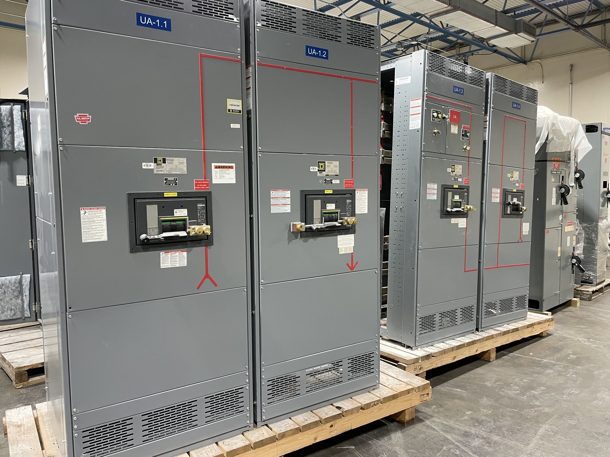
A useful quote package identifies each circuit, CT quantity and location, primary and secondary ratings, ratio, accuracy or performance requirement, core count, terminal arrangement and associated relay. Include drawings or a one-line diagram, equipment interface dimensions, system data and applicable project specifications. State what remains undecided instead of allowing assumptions about ratio, burden or fault duty to pass unnoticed into the order.
For a Georgia project, provide the jobsite destination, required delivery sequence, receiving constraints and the date the switchboard must be available for installation. Delivery planning can be coordinated with the overall equipment order, while exact configuration, component availability and schedule are confirmed for that order. Before release, review the CT schedule, wiring and relay interfaces together; then return approved, current documents with any changes clearly marked.