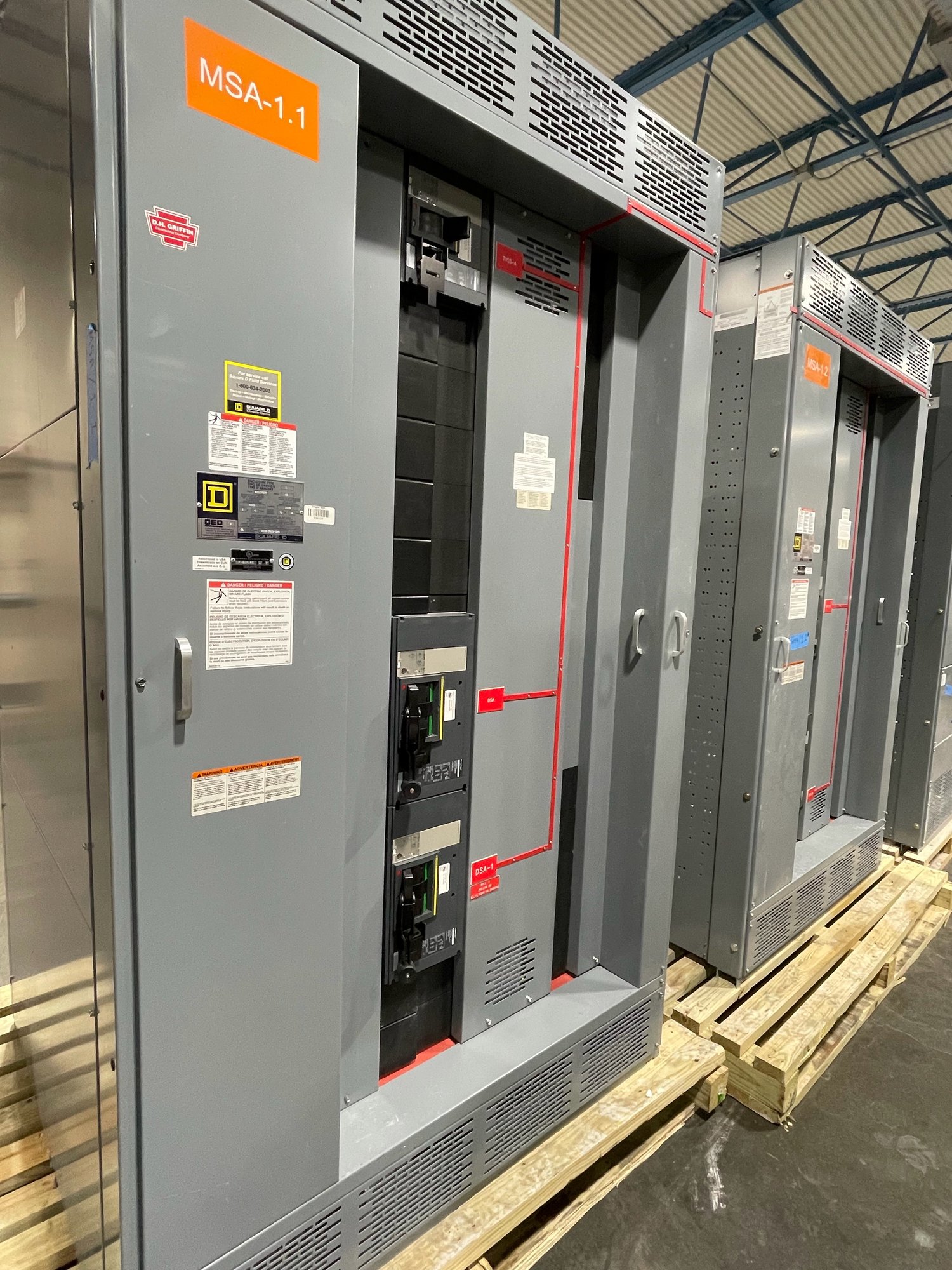
Reliability begins with load priorities
Start by identifying what must remain available during a utility interruption or equipment outage. A facility may distinguish security electronics, control rooms, communications, emergency lighting, medical spaces, kitchens, and administrative loads. The owner’s electrical engineer should document these priorities, applicable code requirements, operating modes, and acceptable interruption or transfer sequence. That load schedule gives switchgear planning a practical basis without assuming every facility has the same critical systems.
Ask how the electrical arrangement is expected to respond to a fault or planned work. Main and feeder devices, bus arrangement, source connections, metering, and protective-device coordination affect which portions of a facility can be isolated. Where continuity is important, review selective coordination and arc-flash study requirements with the responsible engineer. Final equipment ratings and settings depend on the available fault current, system voltage, and project-specific engineering.
Design access around security procedures
Electrical rooms in secure facilities may be subject to escort rules, controlled keys, entry logs, tool restrictions, and limits on when work can occur. Share these constraints early so the equipment layout, access clearances, door swing, lifting path, and working space can be reviewed against the room and the facility’s security plan. A configuration that fits electrically still needs to be deliverable and serviceable through the actual route.
Discuss who may operate or inspect equipment and what access controls apply to normal and emergency operation. Enclosure arrangement, door hardware, labeling, and separation of operating areas should be reviewed by the project engineer and facility security team. Do not rely on access-control hardware or special operating procedures as a substitute for required electrical protection, qualified personnel, or approved working clearances.
Make maintenance workable in a restricted environment
A maintenance plan should identify inspection intervals, permitted outage windows, isolation points, and the facility approvals needed before work begins. Confirm whether staff can de-energize a section without affecting security-critical loads, and whether temporary operating arrangements are allowed. Switchgear features such as drawout devices, test provisions, and compartment access can influence maintenance tasks, but the selected approach must match the engineered design and the facility’s operating rules.
Ask what records maintenance personnel need at turnover: final one-line diagrams, device schedules, settings documentation, operating instructions, and identification consistent with the installed equipment. Coordinate requirements for cleaning, exercising, testing, and replacement parts with the equipment design and manufacturer documentation. Only qualified personnel should perform electrical work under the facility’s approved safety procedures; access controls should also cover contractors, tools, and work materials.
Coordinate standby and emergency power
Backup power planning begins with the source and load sequence. Confirm whether the facility uses generators, another standby source, or a combination; which loads transfer; whether any loads are shed; and how systems return to normal power. The engineer must determine source capacity, short-circuit contributions, grounding, transfer method, and protective-device coordination. Switchgear connections and controls should reflect the approved one-line diagram rather than an assumed generator arrangement.
Consider operational details such as generator paralleling, maintenance bypass needs, transfer testing, and the consequences of a failed source or transfer operation. Security and facility teams can identify which functions need priority during limited-capacity operation, while the engineer validates the electrical design. Confirm how alarms, status indication, and remote monitoring interfaces should be coordinated with the facility’s systems and commissioning plan.
Specify the assembly and project interfaces
For a low-voltage switchboard, UL 891 is the relevant switchboard standard; it should not be treated as a blanket certification for medium- or high-voltage switchgear. Define voltage, bus and main-device requirements, feeder count, available fault current, enclosure conditions, metering, controls, cable entry, and any future spare provisions. Custom-built configurations and American-made components may be considered where they fit the approved design and availability.
For a useful quote, provide the latest one-line diagram, load and feeder schedules, project specifications, room dimensions, utility data, required interfaces, and requested delivery location in Georgia. Identify the security access process, delivery route, unloading responsibilities, construction schedule, and commissioning milestones. Exact scope, component availability, and timeline are confirmed for each order; Georgia delivery planning should account for site access and receiving limits.
Close the handoff before energization
Before release and installation, align the approved drawings, equipment submittals, protection-study inputs, control requirements, and site dimensions. Resolve changes to feeder counts, source arrangements, or room access before fabrication where possible. At handoff, coordinate shipping documents, receiving inspection, storage conditions, installation responsibilities, and the records required by the owner and engineer. Energization and acceptance testing belong to qualified personnel under the project’s approved procedures.
For the next project review, assemble the one-line diagram, critical-load priorities, backup-power sequence, maintenance access rules, and Georgia site delivery constraints. Ask the engineer and facility team to confirm these inputs, then request a configuration and schedule based on the defined scope. This focused preparation helps keep security operations, electrical requirements, and procurement decisions aligned.