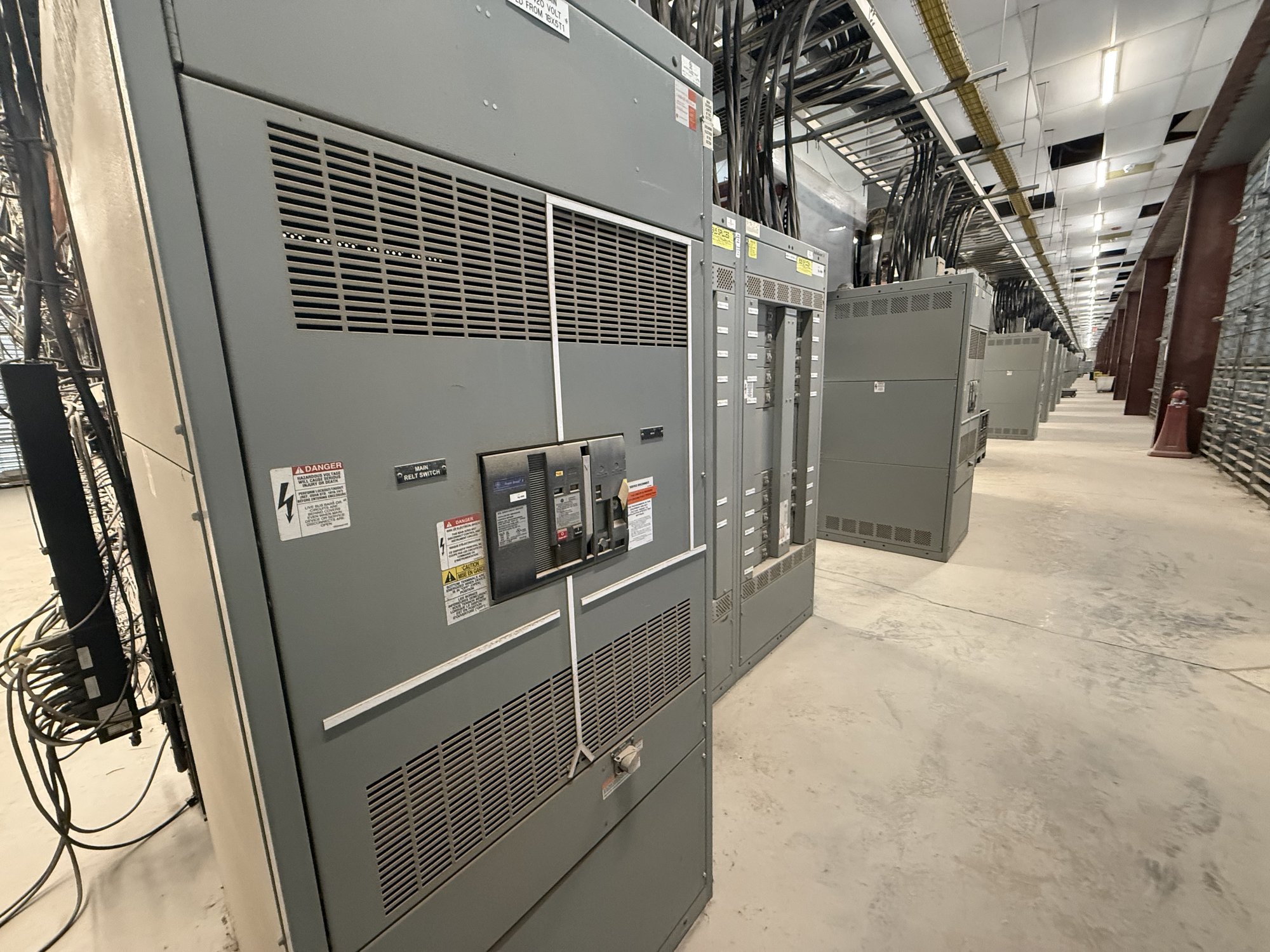
What opening and closing times reveal
An opening test records the interval from an applied trip command to contact separation. A closing test measures the interval from a close command to contact engagement. Depending on the breaker and test setup, a timing instrument may also record each pole separately, showing the relationship between phases and the sequence of auxiliary contacts.
These measurements help assess operating consistency, not simply whether a breaker moves. Excessive variation between poles, unexpected sequence, or a change from prior results may warrant engineering review. Timing alone does not establish the condition of every internal component or prove that a breaker will interrupt a fault at its rated duty.
Define the test and acceptance basis
Before testing, identify the breaker manufacturer, model, serial or asset number, rated voltage and current, and operating mechanism. Confirm whether the request covers opening, closing, trip-free operation, pole spread, or auxiliary-contact timing. The applicable limits and definitions may differ by breaker family and by the manufacturer’s procedure.
Ask for the specific manufacturer document, revision, and acceptance values that will govern evaluation. Clarify whether the criteria apply to total operating time, phase-to-phase difference, or another recorded interval, and whether the test is performed at a specified control voltage. Do not substitute a general rule of thumb for criteria tied to the actual equipment.
Choose a method suited to the breaker
A timing analyzer uses control commands and suitable contact connections to capture operation. The test plan should state whether measurements use main-contact connections, auxiliary contacts, or both, since these points do not necessarily represent the same event. Instrument setup, channel assignment, connection diagrams, and command definitions should be documented so results can be reproduced.
Breaker construction and access affect what can be measured. Drawout position, interlocks, stored-energy mechanisms, trip and close circuits, and control-power arrangements must be understood before work begins. Testing and operation should be performed only by qualified personnel under the site’s safety procedures and equipment-specific instructions; the test method must not bypass safeguards.
Interpret results as a set
A useful report identifies the breaker and test conditions, records the command and contact traces, lists measured times for each pole, and states the criteria used for comparison. Include instrument identification and calibration status where required by the project. If a result falls outside a stated limit, preserve the trace and record the exact operating condition rather than reducing the finding to a pass-or-fail label.
Compare measurements with the correct manufacturer criteria and, when available, the breaker’s prior baseline under comparable conditions. Differences can be influenced by control voltage, mechanism condition, setup, and measurement definitions. A deviation calls for investigation by the responsible engineer or service professional; timing data by itself does not diagnose a specific defect or authorize adjustment.
Plan procurement and project handoff
For a new switchboard or replacement project, define whether timing-test documentation is a required submittal, factory test record, or separate field-service deliverable. State the equipment identification, test scope, report format, applicable manufacturer criteria, and any witness or hold-point requirements in the procurement documents. Confirm which records are available for the specific configuration before the order is finalized.
For a project in Georgia, share the delivery location, site receiving constraints, required arrival window, and coordination milestones when requesting a quote for new equipment. Delivery timing and documentation depend on the confirmed order scope and schedule. Ask how the supplied records will identify the breaker, test method, results, and acceptance basis so the project team can connect them to commissioning files.
Prepare a clear request
A focused request should include the breaker make and model, quantity, voltage class, control-voltage information if known, required opening and closing measurements, and the manufacturer criteria or document reference. Add drawings or nameplate data when available, plus the intended use of the results: procurement review, factory documentation, commissioning, or maintenance comparison. This lets the team identify information gaps without assuming a design.
Before approving a scope, confirm who supplies the acceptance limits, how exceptions will be reported, and what records will accompany the equipment. Send the breaker details, required test scope, applicable criteria, and Georgia delivery needs with the quote request. Resolve any missing manufacturer data with the responsible engineer before treating a timing result as acceptable.