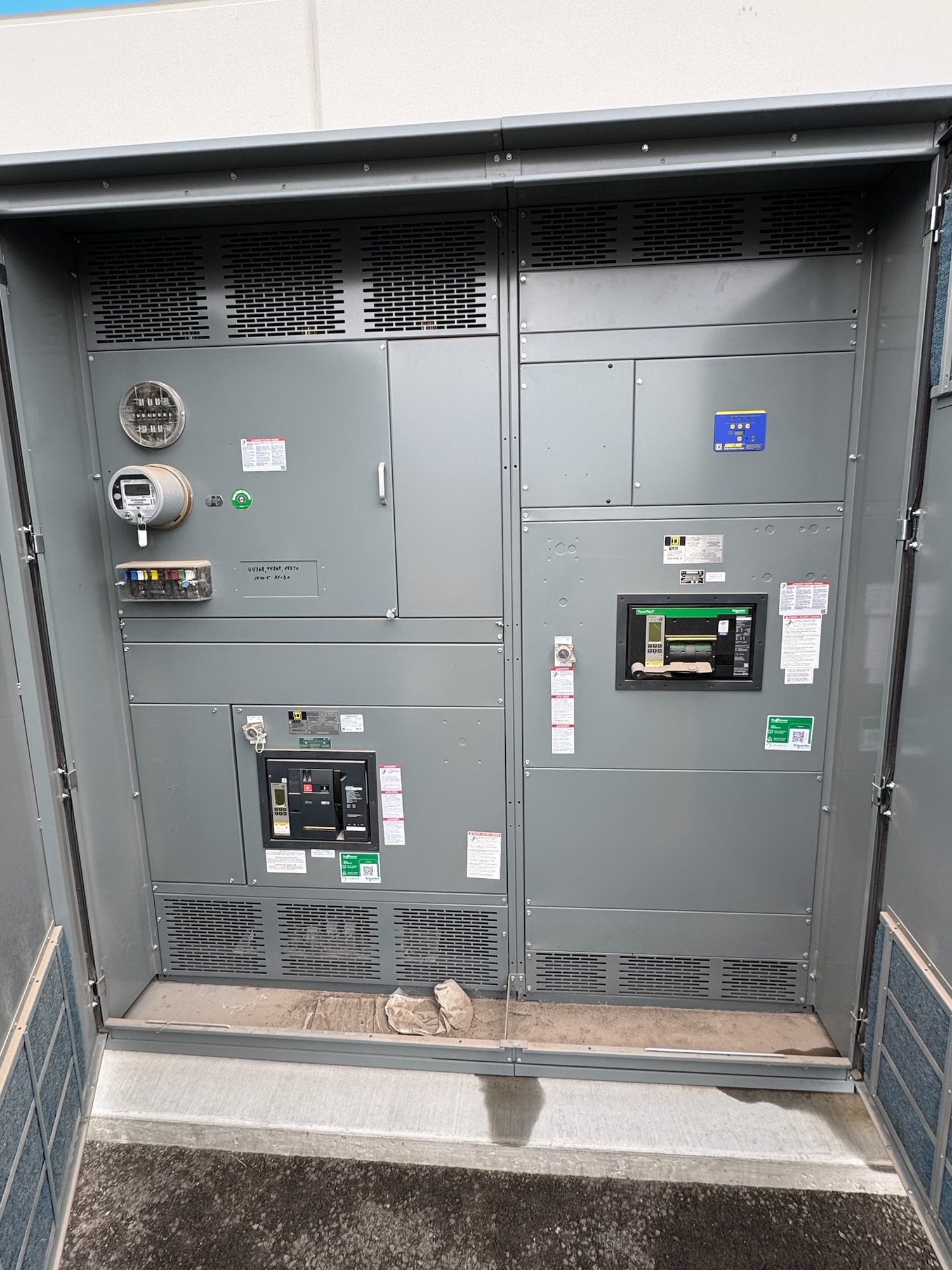
Map sources, buses, and critical loads
Start with a one-line diagram showing the utility point of connection, generators, battery energy storage system, campus buses, and major load groups. Identify normal and alternate power paths, planned tie points, and any loads that must remain separated. The diagram should distinguish equipment included in the switchboard package from transformers, source equipment, controls, and field wiring provided by others.
List source voltage, phase, frequency, available fault-current information, and expected operating modes as determined by the project engineer. Also identify present loads and planned campus expansion. A phased project may need reserved spaces or provisions for future connections, but those provisions depend on the chosen lineup and require engineering review; do not assume spare capacity or a future source can be accommodated without design changes.
Coordinate generation and storage connections
Generator and battery interfaces require more than a breaker position. Clarify whether sources connect to a common bus or separate sections, how paralleling is controlled, and what signals are exchanged with the microgrid controller. Battery system limits, inverter characteristics, charging modes, and the energy storage supplier’s interface requirements can affect breaker selection, protection coordination, and the equipment arrangement.
For each source, provide available fault-current contributions, grounding method, operating range, and the intended connection point. Confirm who supplies protective relays, metering, interposing devices, and control wiring, and which party verifies compatibility. Switchboard assemblies built to UL 891 apply to switchboards within that standard’s scope; that designation does not establish suitability for every source interface or certify the entire microgrid.
Define islanding and transition behavior
Describe what initiates islanding, which device separates the campus from utility service, and what conditions permit reconnection. The project engineer and utility must establish the operating sequence, permissives, synchronization requirements, and transfer logic. Switchgear can provide the specified switching and interface points, but controls behavior depends on the complete engineered system and coordination among the owner, controls integrator, utility, and equipment suppliers.
Ask how the campus will handle load shedding, source loss, black start, and return to grid operation. Identify whether transitions are open or closed, whether parallel operation is permitted, and how the design prevents unintended energization of utility conductors. These decisions influence control compartment needs, auxiliary power, interlocks, and test planning. Final settings, operating procedures, and acceptance criteria belong in the coordinated project documents.
Resolve protection and utility interfaces
Microgrid protection must account for changing fault levels and current direction as sources connect or disconnect. Share the available utility fault data, generator and inverter contribution data, grounding study, relay philosophy, and coordination study assumptions. The responsible protection engineer can determine whether protection needs mode-dependent settings, directional elements, communications, or other functions; equipment scope should follow that engineered decision rather than presume a standard arrangement.
Confirm the utility’s interconnection requirements and the authority having jurisdiction’s review process with the project team. Establish ownership of revenue metering, utility-visible disconnects, relaying, communications, and witness testing. Requirements can vary by service arrangement and project, so include written utility comments and approved design documents in procurement coordination. No equipment description alone establishes code compliance or utility acceptance.
Specify the lineup for campus conditions
Procurement documents should state the required voltage and current ratings, bus configuration, short-circuit withstand or interrupting requirements as applicable, enclosure location, access clearances, cable entry, and environmental conditions. Include room dimensions, floor and anchorage constraints, seismic or other project criteria when applicable, and the planned route from unloading point to electrical room. These details help establish a buildable lineup and avoid late revisions.
A custom-built configuration can align sections, source connections, metering, and controls with the campus one-line and room layout. Identify which components must be American-made, any specified makes or approved alternatives, and whether substitutions require review. Confirm availability, exact scope, and production timeline for the order; do not base campus commissioning milestones on assumed stock or an unverified lead time.
Prepare a complete Georgia project handoff
For a quote, provide the latest one-line diagram, load and source schedules, equipment ratings, protection requirements, control narratives, utility interface documents, room plan, cable approach, and requested delivery milestone. State the campus location in Georgia, receiving access, unloading responsibilities, and whether delivery must coordinate with construction phases. Nationwide shipping can serve Georgia projects, while routing and delivery details are confirmed for each order.
Before release, align the approved drawings with the controller and relay interface lists, breaker and accessory schedule, terminal requirements, and responsibility matrix. Name the parties responsible for settings, field connections, startup, and functional testing so the switchgear package hands off cleanly into system commissioning. Send the coordinated project documents and delivery constraints with the quote request; that gives the manufacturer a defined basis to confirm configuration, scope, availability, and timeline.