Define the two power sources
Start with the normal and alternate sources, then document the electrical characteristics of each: voltage, phase, frequency, available fault current and grounding arrangement. The alternate source may be a generator, a second utility feed or another engineered supply. Confirm whether sources are independent and whether the alternate source can support the loads intended for transfer; an ATS cannot make an undersized source adequate.
Share source capacity, generator starting and load-acceptance information when applicable, along with the normal source limits that should initiate transfer. Identify whether the system needs open-transition, closed-transition or another defined operating sequence. Source details and operating intent let the manufacturer evaluate a suitable configuration rather than assume that two nominally matching supplies behave the same.
Choose transition behavior for the load
Open-transition switching disconnects one source before connecting the other, producing a brief interruption. It is often appropriate where loads can tolerate that break. Closed-transition switching momentarily parallels sources during transfer and requires compatible sources and an approved operating scheme. Its use depends on utility requirements, generator controls, protection and project engineering; it is not simply a convenience setting.
Some applications need delayed transition, in-phase transfer or a programmed sequence to limit electrical or mechanical effects on connected equipment. Motors, elevators, process controls, UPS systems and sensitive electronics can respond differently to an interruption or source change. List critical loads and acceptable interruption behavior so the engineer can determine whether staged transfer, load shedding or separate transfer groups are needed.
Coordinate protection and distribution
The ATS must fit the distribution path around it. Provide the one-line diagram and identify upstream overcurrent devices, downstream switchboards or panelboards, feeder sizes and the loads served. Coordination review should consider device ratings, available fault current, selective operation where required, and the protection approach for each source. The transfer switch’s rating and short-circuit withstand or closing capability must be evaluated against the actual system conditions.
Clarify whether the neutral is switched and how the sources are grounded, especially where a generator is separately derived. Neutral switching, ground-fault protection and bonding affect system behavior and must be reviewed together by the responsible electrical engineer. If the ATS feeds a switchboard assembly, define incoming and outgoing arrangements, space needs, metering or control interfaces, and the division of scope between equipment packages.
Specify controls, signals and operating needs
Describe how the switch should detect an unacceptable normal source, start the alternate source, transfer loads and return to normal power. Relevant settings may include source-failure thresholds, time delays, retransfer behavior and cooldown sequence. Identify required remote status, alarms, generator start contacts, building-management connections and any communication protocol. Control details should be confirmed against the selected equipment and the project’s sequence of operations.
Also state the intended environment and installation constraints, including indoor or outdoor location, enclosure needs, available working space and cable-entry direction. Provide the required current rating, pole configuration and any metering or accessory requirements without assuming a particular model. Engineering review must confirm that the final selection and installation meet project requirements and applicable authority decisions.
Prepare a complete quote request
For a useful quote, send the one-line diagram, load schedule, source data, fault-current information, transition preference and written sequence of operations. Include the project location in Georgia, required delivery point, target schedule, equipment dimensions or room constraints, and the planned interface with downstream distribution. Identify open design questions rather than filling gaps with assumptions; exact configuration, availability and timeline are confirmed for each order.
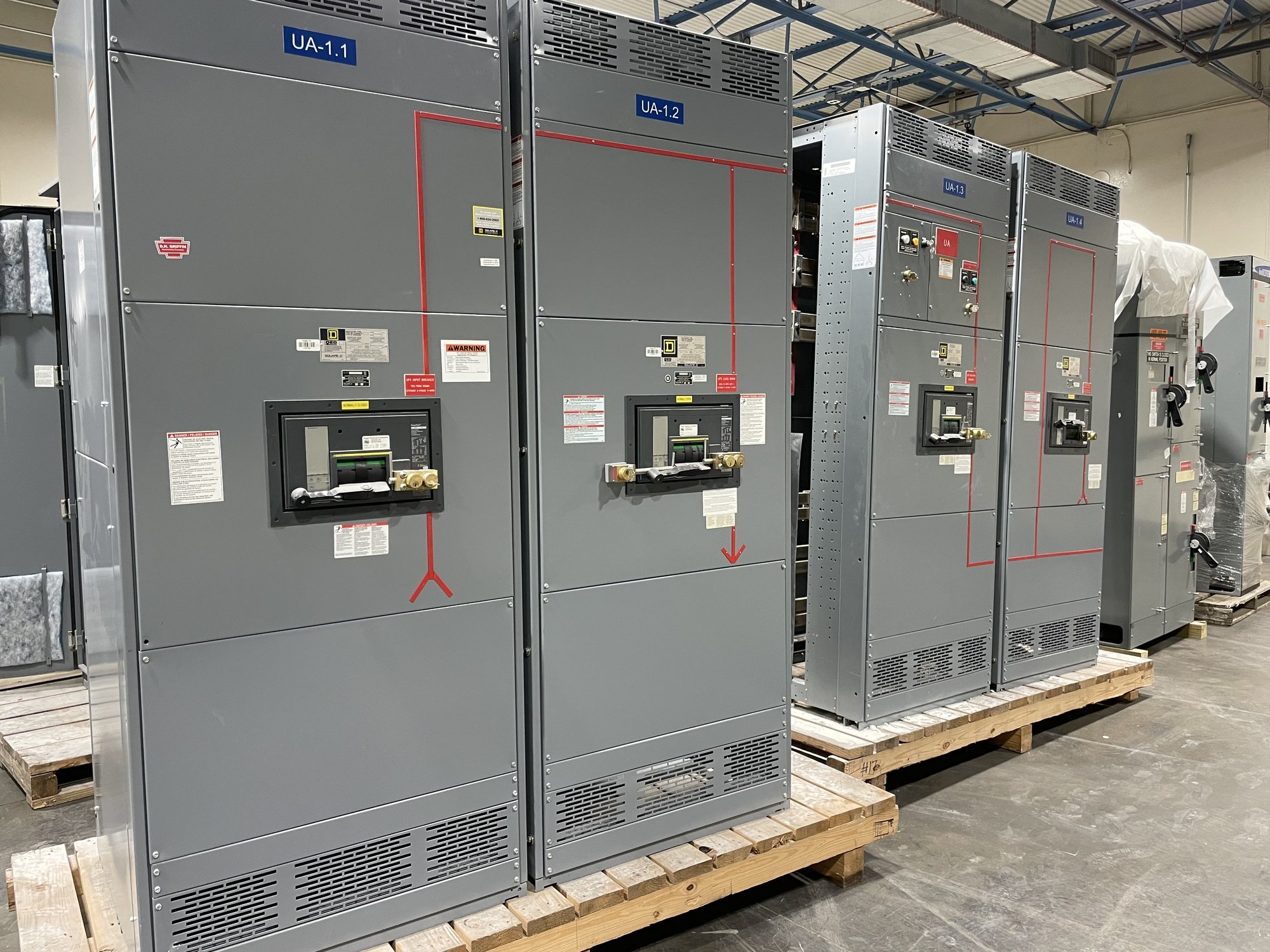
Our team builds and supplies new electrical equipment in the United States, with custom configurations, American-made components and nationwide shipping options. For an ATS package, the handoff should capture approved drawings, connection details, control interfaces and the equipment scope needed by the installing contractor. Delivery planning for a Georgia project should align with site access, receiving arrangements and the construction schedule; confirm these details during order coordination.
Close the design loop before release
Before equipment release, have the responsible engineer verify source compatibility, load capacity, protection coordination, grounding and the intended transfer sequence. Resolve utility or generator requirements and obtain required reviews from the authority having jurisdiction. Final drawings should make clear what the ATS controls, what it supplies and which functions belong to separate generator, switchboard or building-control equipment.
To move the specification forward, provide the latest one-line, source and load data, preferred transition method, control requirements and Georgia delivery constraints. Ask for a configuration review against those project documents, then coordinate drawing approval and schedule before release. This creates a clear basis for purchasing a new transfer-switch assembly and integrating it with the distribution equipment it is meant to serve.