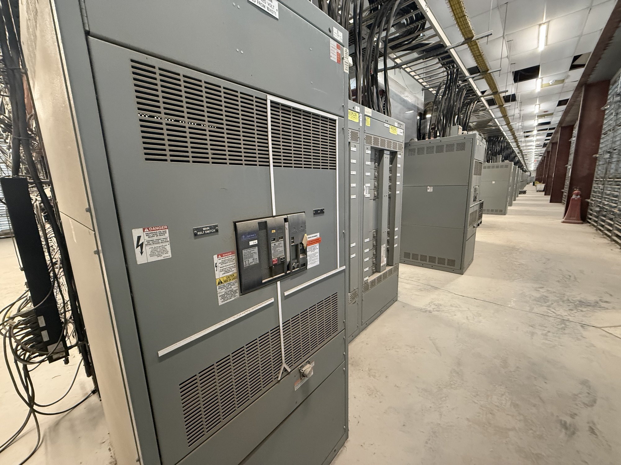
Start with the service and load basis
Confirm what the 2,000-amp rating represents in the project: the incoming service, a main device, or a distribution section downstream of another source. Share the system voltage, phase and wire arrangement, available fault current, grounding method, source information and any applicable utility requirements. These details establish the design basis; the ampere rating alone does not define an acceptable assembly.
Provide a current load summary and identify expected additions, such as future tenant spaces, process equipment or building expansions. The engineer should determine demand, diversity and required capacity rather than treating the full main rating as usable capacity for every feeder. If the project includes parallel sources, tie breakers or standby generation, explain the intended operating modes so the configuration can be reviewed against the actual system.
Coordinate feeder count and capacity
A useful feeder schedule identifies each load, its voltage, required breaker or fusible-switch rating, conductor information where established, and whether the circuit is new, spare or reserved for future use. Include the desired number of poles, trip or fuse requirements, and any project-specific control or interlocking needs. This lets the assembly layout account for feeder quantity and device space instead of relying on a general statement that more circuits may be needed.
Balance feeder capacity against section dimensions, cable entry, conductor bending space and the location of incoming and outgoing connections. Large conductors can affect wireway and compartment arrangements, while many smaller feeders can drive a different section layout. Submit the one-line diagram and panel or equipment schedules together, and flag loads whose protection or coordination requirements remain under engineering review. Final device selection and ratings depend on that review.
Set the metering arrangement early
Specify whether the project needs utility revenue metering, owner monitoring, or both. Identify the party setting the requirements and provide any available metering diagrams, utility service criteria, instrument-transformer requirements, meter location rules and communications expectations. Revenue-metering details can affect section space, barriers, wiring access and the relationship between the service disconnect and meter compartment.
For facility monitoring, clarify which values and circuits should be measured, where data must be made available, and whether meters need network communications or local indication. Do not assume that a meter, communications protocol or utility-accepted compartment is included by default. Review the proposed arrangement with the engineer and utility as applicable before release, then record required accessories and interface responsibilities in the approved submittal.
Define ratings and assembly scope
Request review of nominal voltage, continuous current, short-circuit withstand or interrupting requirements, enclosure type, bus material and finish, and the intended installation environment. Available fault current and protective-device characteristics are essential inputs for evaluating the assembly and its devices. Do not select a rating from the 2,000-amp description alone; the project engineer and authority having jurisdiction must review the design against site conditions and applicable requirements.
For a UL 891 switchboard assembly, identify that scope explicitly and confirm the proposed assembly configuration and documentation during submittal review. UL 891 applies to switchboards; it is not a blanket listing for medium- or high-voltage switchgear. If the project involves equipment outside switchboard scope, state the voltage class and required equipment type at inquiry so the manufacturer can assess the requested configuration accurately.
Plan the room, route and Georgia delivery
Provide the electrical-room plan, clear working-space constraints, wall and floor conditions, cable entry directions, and any limits on assembly height, depth or section width. Identify the access path from the receiving point to the final room, including door and corridor dimensions, turns, elevators, loading-dock limits and lifting restrictions. A layout that fits the electrical room still needs a feasible route for delivery and placement.
For a Georgia project, share the jobsite city, receiving hours, site access rules, unloading capability, preferred delivery window and whether sections must be handled separately. Nationwide shipping can be coordinated for the order, but the route, packaging, shipment configuration and schedule must be confirmed for that project. State who will receive, unload and move the equipment, and raise site restrictions before the shipping plan is finalized.
Make the quote and handoff specific
For a practical quotation, send the one-line diagram, feeder schedule, load basis, system voltage, fault-current information, metering criteria, room drawings, requested documentation and target project milestones. Note which details are approved and which remain provisional. Also identify the purchasing entity, ship-to location, unloading arrangements and any required submittal or inspection milestones. The manufacturer can then evaluate a custom-built configuration and clarify scope, availability and timeline for the order.
Before release, reconcile the quotation and approved drawings against feeder devices, metering provisions, dimensions, entry points, ratings and delivery constraints. Name the parties responsible for utility coordination, engineering approval, installation and site receiving. Ask for written confirmation of open items and required inputs, then resolve them before fabrication proceeds. This focused handoff helps keep a 2,000-amp distribution package aligned with the electrical design and the Georgia jobsite plan.