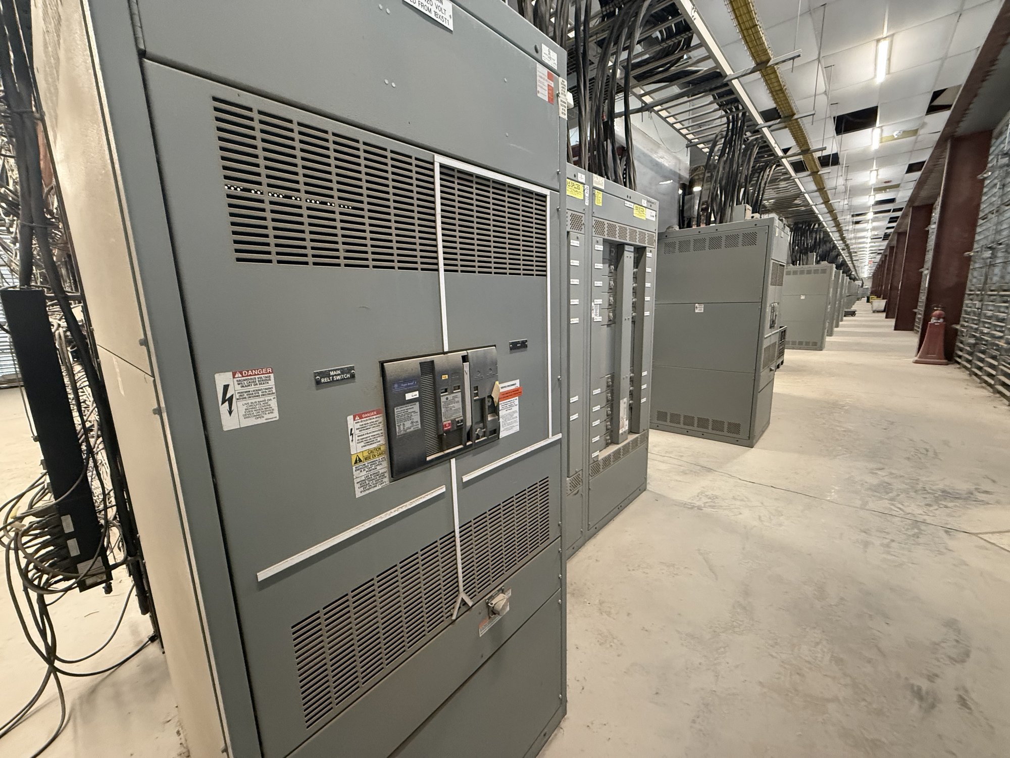
Define the paths to be verified
A continuity check is meaningful only when the required path is clear. Depending on the assembly design, specified paths may include the equipment grounding bus, enclosure sections, doors or covers with bonding provisions, and connections between shipping sections. The design documents should identify which conductive parts are required to bond together and how those connections are made. Do not assume that a visible metal-to-metal joint alone establishes the intended path.
For a new switchboard, distinguish the grounding and bonding features built into the assembly from the grounding electrode system and field conductors installed at the project site. Assembly verification does not establish that the complete installed system is correct. Share the one-line diagram, grounding details, general arrangement, and applicable project specifications so the manufacturer can review the requested factory scope against the actual configuration.
Set acceptance criteria before release
Specifications should state which points are to be checked, the test method or project procedure, the acceptance criteria, and the documentation required. If the engineer has specified a resistance limit or other measurable criterion, provide its source and the relevant test conditions. Avoid inserting a generic value without engineering justification: results depend on the defined path, connection interfaces, test equipment, and method.
Clarify whether verification applies to each section, selected representative paths, or specific interfaces identified in the drawings. Ask whether the project expects continuity checks after assembly, after shipping splits are rejoined, or both. These decisions affect test planning and record format. Any test procedure or acceptance threshold must be reviewed by qualified personnel and coordinated with the engineer of record and the applicable authority.
Account for joints and removable parts
Ground continuity can depend on details that are easy to overlook during procurement: bolted section joints, bonding straps, plated contact surfaces, hinges, removable panels, and field-installed links. The design should identify intended bonding hardware and connection points rather than relying on incidental contact. Where a door or cover has a specified bonding conductor, the verification plan should address that path in the configuration required by the project.
Shipping splits create a separate handoff issue. A factory check on an assembled lineup may not verify the path after sections are separated for transport and reconnected in Georgia. Identify which links, hardware, or conductors will be removed for shipment and who will install them at the site. Provide installation instructions and inspection or test requirements for those interfaces so the field team can complete the intended grounding connections.
Coordinate testing with assembly scope
A useful quote request identifies the assembly type, section count and arrangement, project drawings and revisions, grounding-bus details, and any specified continuity procedure or acceptance limit. Include the required test points, whether shipping splits are involved, and the records expected with delivery. If the grounding design is still under review, mark the open items rather than treating an assumed arrangement as final.
New UL 891 switchboard assemblies can be configured to project requirements, but UL 891 applies to switchboards and does not establish a blanket certification for other classes of switchgear. State the equipment category and requested verification separately. The exact assembly scope, test capability, documentation, availability, and schedule are confirmed for each order; a requested test should not be represented as included until it is agreed in the order documents.
Make records useful at the jobsite
A practical report identifies the assembly or section, test date, procedure or method, points checked, equipment used where required by the specification, results, and acceptance basis. Record exceptions and corrective work clearly, then document any repeat checks. This gives the receiving team a traceable factory record without implying that it replaces field inspection, installation checks, or approval required by the project.
For Georgia delivery, coordinate the report package with the shipment documents and the project’s receiving process. Confirm who will inspect the assembly on arrival, who will reconnect shipping splits, and what field verification is required before energization. Delivery timing and configuration are order-specific, so align the requested records and site sequence with the confirmed shipment plan rather than assuming a standard handoff.
Close the specification gaps
Before requesting pricing, gather the latest drawings, grounding and bonding requirements, test points, acceptance criteria, report format, shipping-split details, delivery location in Georgia, and required on-site sequence. Identify any project-specific inspection or authority review. These answers help resolve whether the requested verification belongs at the factory, in the field, or in both stages, and prevent the purchase documents from leaving important responsibilities unstated.
Ask the project engineer to approve the continuity scope and criteria, then submit those requirements with the configuration for review. Confirm which paths will be checked, which connections must be completed after shipment, and what evidence the receiving team needs. That focused handoff gives installers and facilities personnel a clear basis for completing the specified grounding work before the equipment is placed in service.