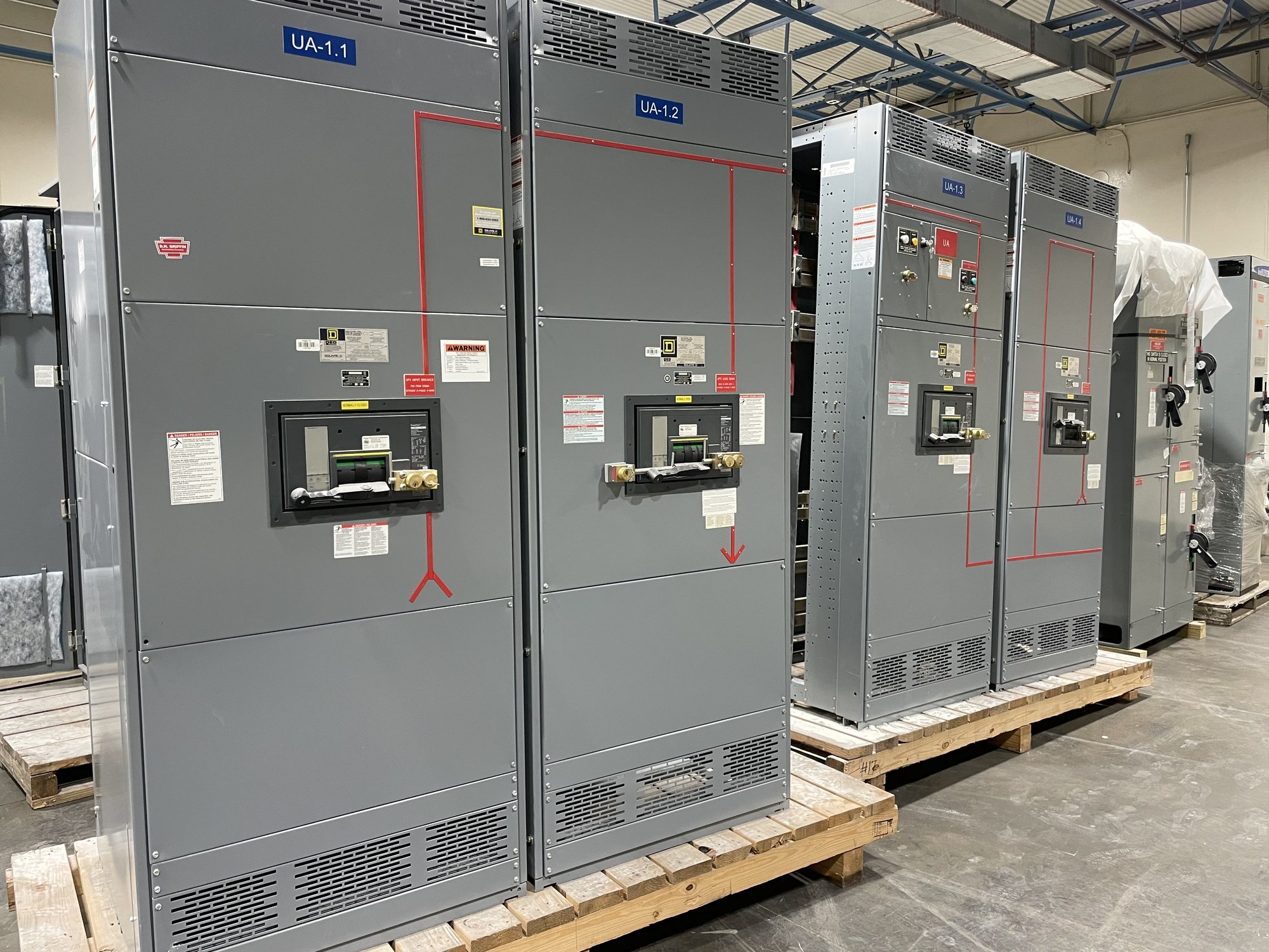
How the assembly is organized
A typical assembly receives power at an incoming section, distributes it across bus, and feeds downstream loads through individual protective devices. Depending on the design, sections may contain main, tie and feeder breakers, metering, control components, or provisions for future circuits. The one-line diagram is the starting point: it shows sources, buses, ties, feeder destinations and the intended operating arrangement.
Construction details affect access and coordination as much as the one-line. Specify the number and width of sections, cable entry direction, conductor landing space, front or rear access needs, and whether equipment must align with existing gear. Share room dimensions, door and aisle constraints, environmental conditions, and the location of incoming and outgoing conduits. A custom-built layout can be developed around those requirements, subject to design review and confirmed scope.
Choosing protective devices
Circuit breakers are selected for the circuit’s function and electrical duty, not simply by frame size. Air circuit breakers are commonly considered for service mains and ties where adjustable protection, coordination, or drawout maintenance features matter. Molded-case breakers may suit feeder applications when their interrupting capability and trip functions match the calculated fault current and protection study. Device options can include fixed or drawout construction, electronic or thermal-magnetic trip units, and accessories such as shunt trips or auxiliary contacts.
The engineer should define continuous current, short-circuit current, protection functions, coordination objectives, and any required communication or status points. Consider selective coordination, arc-flash analysis, ground-fault protection where applicable, and the effects of alternate sources or generators. A breaker’s interrupting rating must be appropriate for the available fault current at its installation point; a catalog rating alone does not establish suitability. Provide the study assumptions and device preferences for review rather than selecting protection from load amperage alone.
Ratings and standards to confirm
Specify nominal system voltage, frequency, phase and wire configuration, along with the assembly’s continuous current and short-circuit withstand or interrupting requirements as applicable to the design. The available fault current, grounding method, source configuration and protective-device characteristics influence the required ratings. Clarify whether the project calls for service-entrance equipment, a main-tie-main arrangement, or a particular bus configuration, and identify the intended future expansion, if any.
UL 891 applies to switchboard assemblies; it is not a blanket listing for all switchgear or for medium- and high-voltage equipment. Confirm the requested product type, applicable standard, construction scope and any project specifications with the engineer and authority having jurisdiction. Ratings and construction are established for the specific assembly and configuration. Do not assume a rating, certification, or approval from a general product description; obtain and review the documents applicable to the proposed equipment.
Where facilities use it
Low-voltage assemblies commonly serve commercial buildings, industrial plants, campuses, data and communications facilities, water and wastewater operations, and other sites distributing power at utilization-level voltages. They can provide a central point for service distribution, large motor or process feeders, building sections, or connections to downstream panelboards and motor control equipment. The appropriate arrangement depends on load criticality, source redundancy, operating practices and available space.
Georgia projects may involve new construction, capacity expansion, replacement, or a change in service arrangement. In each case, existing conditions can limit the practical design: available fault current may change with a utility or generator source, while room access and shutdown windows can constrain section dimensions and installation sequence. Confirm who is responsible for field verification, outage planning, terminations, commissioning, and coordination with utility or site personnel before equipment scope is finalized.
Prepare a useful project package
For a quote, provide the latest one-line diagram, load and feeder schedules, system voltage, available fault-current data, protective-device requirements, and any coordination or arc-flash study criteria. Include section arrangement, bus requirements, metering and control needs, cable entry and landing details, preferred device features, and applicable project specifications. Identify exclusions, interfaces with existing equipment, and requested documentation so the proposed scope can be compared accurately.
Also share the project location in Georgia, required delivery point, site access limitations, receiving and unloading arrangements, and the target installation sequence. These details help plan nationwide shipping and clarify how the assembly must arrive for the contractor’s work; delivery timing and equipment availability are confirmed for each order. Before release, have the responsible engineer review the drawings, ratings, device selections and interfaces, and resolve comments with the manufacturer. This handoff reduces avoidable changes between procurement, fabrication and installation.