Map the complete plant load
Begin with the electrical one-line diagram and an equipment schedule that identifies each chiller, condenser-water pump, chilled-water pump, cooling-tower fan and auxiliary load. Record motor horsepower, voltage, phase, full-load current, nameplate data when available, quantity, and whether each load is essential or standby. Include control power, heaters and other connected loads where they affect the switchboard arrangement.
Chiller nameplate current alone does not define the plant’s electrical requirements. Ask the mechanical and electrical teams for manufacturer electrical data, minimum circuit ampacity, maximum overcurrent protection and any required disconnecting or control provisions. Confirm which motors are supplied from the switchboard, which have separate drives or starters, and whether future chillers or pump capacity must be accommodated.
Match the assembly to starting methods
A compressor may use across-the-line starting, reduced-voltage starting or a variable-frequency drive, depending on the chiller design and project requirements. Pumps and fans may use direct starters, soft starters or drives. Each method changes the equipment arrangement and affects how the loads behave during startup; do not assume that all motors in a plant use the same approach.
For each motor, identify the starter or drive type, who supplies it, and where it will be installed. If the switchboard includes motor-control sections, define the required compartments, control interfaces and isolation provisions. If separate equipment handles motor starting, show the connection and upstream protective device requirements. Final selections should be coordinated by the project’s qualified electrical and mechanical design teams.
Coordinate sequence and simultaneous demand
The plant control sequence determines which loads can start together and which must wait. A sequence may call for pumps or tower fans to run before a chiller starts, or use staged starts to limit coincident demand. Share the control narrative, interlocks, operating modes and any demand-management strategy so the electrical design team can evaluate the intended sequence rather than size around an assumed startup pattern.
Discuss normal operation, lead-lag rotation, standby equipment and recovery after a power interruption. Multiple chillers restarting together can create a different demand from staged recovery, while a drive’s ramp profile differs from a direct motor start. Confirm what happens during automatic transfer or generator operation, if applicable, and whether control logic prevents starts that exceed the project’s source or operating limits.
Establish available fault current
Available fault current at the switchgear depends on the utility source, transformer characteristics, conductors and upstream equipment. The design engineer should provide the calculated value at the proposed line terminals, along with the system voltage and grounding arrangement. If a generator, alternate source or future transformer change is planned, identify it early because source conditions can affect equipment selection and coordination.
Compare the calculated fault current with the assembly’s applicable short-circuit rating and the ratings of connected devices. Do not infer an acceptable rating from the chiller’s motor current or from a switchboard standard. Protection coordination, interrupting ratings and any series-rated combination require engineering review for the actual configuration and fault-current study. Provide the study basis and flag pending utility data before procurement is finalized.
Define the build and project handoff
For a quote, share the one-line diagram, load and motor schedules, chiller and drive submittals, control sequence, fault-current information, enclosure location, service entrance details and required interface points. Note space constraints, cable entry direction, metering or communications needs, spare provisions and the project schedule. Identify which documents remain preliminary so assumptions can be resolved before release.
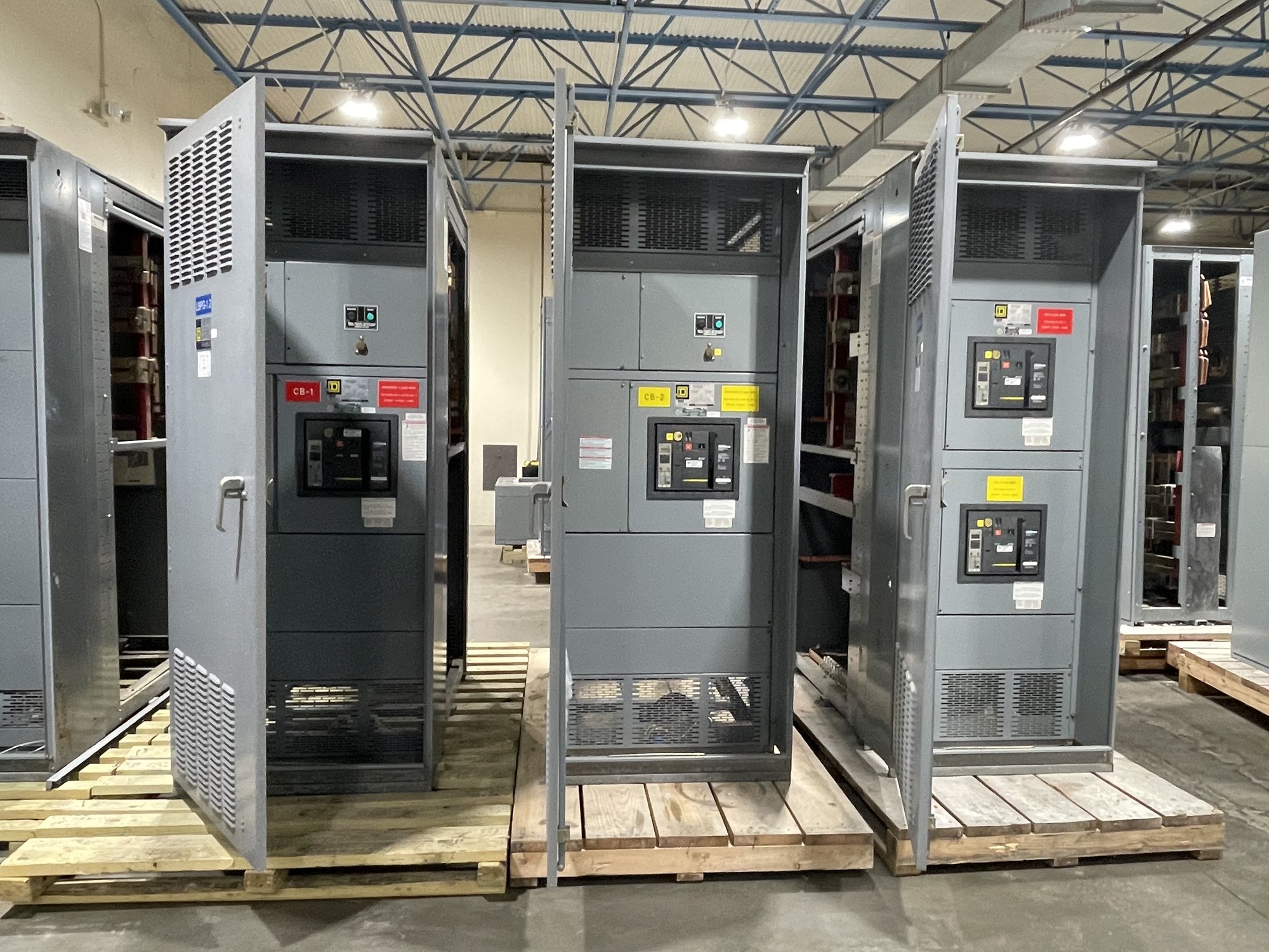
New switchboard assemblies can be custom built around the approved project requirements, with UL 891 applicable to switchboard assemblies when specified and verified for the offered configuration. That standard does not provide a blanket listing for medium- or high-voltage switchgear. Confirm the exact scope, component availability and production timeline for the order. Georgia delivery can be coordinated with the site’s access, receiving hours, unloading capability and installation sequence; confirm these logistics during order planning.
Close the specification gaps
Before authorizing fabrication, have the responsible engineers reconcile the final one-line, motor data, starter and drive scope, operating sequence, source assumptions and fault-current study. Resolve discrepancies between mechanical schedules and electrical documents, and identify any owner-furnished controls or equipment. The approved submittal should show the configured assembly and the interfaces needed by the field installation team.
To start a project-specific quote, send the latest electrical documents and mark the chiller loads, starting methods, sequencing constraints and available-fault-current value or study status. Include the Georgia delivery location and target receiving window. This gives the manufacturer a clear basis to confirm the proposed configuration, open technical questions and order timeline before the project moves into procurement.