Specify the joint, not just the bar
A useful joint specification identifies the conductors being connected, their material, dimensions, orientation and intended overlap. It should also show whether the connection is bar-to-bar, bar-to-terminal or part of a transition between sections. Drawings need enough detail to establish hole locations, edge distances, clearances and access for assembly and inspection. A bus size alone does not define a complete joint.
The joint’s electrical and mechanical requirements depend on the assembly design and application. Share relevant drawings, equipment ratings, connection points and any project-specific design criteria for engineering review. Avoid assuming that a familiar joint pattern or hardware arrangement is suitable for a different conductor material, geometry or duty. The approved design should govern fabrication and assembly.
Control contact surface condition
Contact faces should be clean, flat and free of burrs, embedded debris, oil, oxidation or damage that could interfere with the intended interface. Fabrication methods can leave sharp edges, raised material or distortion around holes; these conditions need to be identified and addressed under the approved process before assembly. Protect prepared surfaces from contamination during handling and storage.
Surface treatment is design-dependent. Plating, compounds, cleaning methods and any limits on removing material should be specified or confirmed by the responsible engineering authority. Do not improvise abrasives, solvents or joint compounds: an unsuitable method can alter a finish, leave residue or compromise the interface. When existing conductors or field conditions are involved, document their actual condition for evaluation rather than assuming they match new fabrication.
Match hardware to the approved design
Fastener material, diameter, length, grade, washers and locking features should be selected as a coordinated set. Hardware must provide the specified clamping arrangement without bottoming out, interfering with adjacent parts or reducing required clearance. Where dissimilar conductive materials meet, the design should address material compatibility and any required interface provisions instead of relying on a general-purpose bolt selection.
Procurement documents should identify the required hardware and its applicable specifications, along with any restrictions on substitutions. Confirm that supplied hardware matches the approved bill of materials and that washers or other components are oriented as detailed. For quote review, provide the joint drawings, conductor materials, hardware requirements and any project standards. If requirements are not established, flag the open items for engineering resolution before release.
Design for fit and access
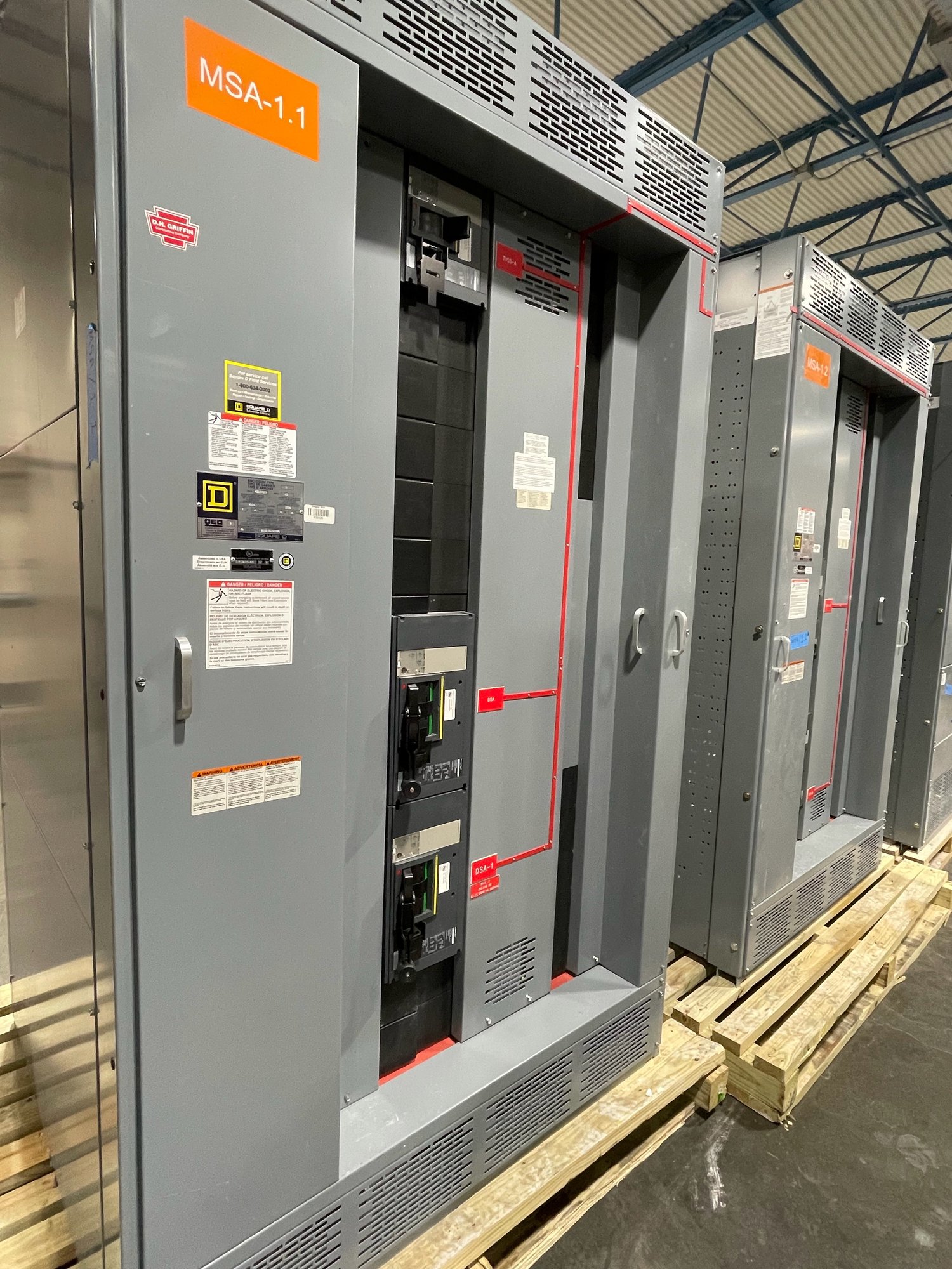
Joint geometry affects more than contact area. Hole pattern, overlap, bar alignment, support locations and nearby barriers all influence whether the connection can be assembled without forcing parts into position. Designs should account for tool access and a clear inspection path, including at joints inside enclosures or between switchboard sections. Forced alignment can introduce stress or conceal a fit problem.
Review tolerance accumulation across the full connection, especially where multiple bars, transition pieces or section interfaces meet. Drawings should identify critical dimensions and distinguish fixed features from permitted adjustment. For replacement interfaces or connections to equipment supplied by another party, confirm mating dimensions and interface details rather than relying on nominal dimensions. Final suitability remains subject to the project’s engineering review.
Make assembly repeatable and inspectable
An assembly procedure should define the sequence for preparing the surfaces, aligning the bars, installing hardware and tightening fasteners. Where the design specifies a torque value or tightening method, use the approved value and a suitable, controlled tool; do not substitute a generic torque chart for design direction. Record required checks in the applicable quality documentation.
Before closure, inspect that contact faces are seated as intended, hardware is complete and correctly oriented, and no debris or foreign material remains. Verify alignment and clearance against the approved drawings. Any gap, distortion, damaged finish or mismatched hardware should be referred for disposition rather than corrected by unapproved rework. Inspection records help connect the finished joint to its design and assembly requirements.
Coordinate the order and Georgia delivery
For a new switchboard order, send the latest one-line diagram, bus and joint details, section layout, material and finish requirements, hardware schedule, applicable project specifications and requested delivery sequence. Identify field connections, interfaces supplied by others, drawing approval steps and any site access constraints. These details help establish what can be built, what needs clarification and how the assembly should be prepared for shipment.
We manufacture and supply new switchboard assemblies in the United States, with custom configurations and nationwide shipping. For Georgia projects, coordinate the required delivery location, site receiving conditions, unloading responsibility and installation sequence with the project team; delivery timing and scope are confirmed for each order. Before approving fabrication, resolve open joint details and provide one controlled set of drawings and specifications. That handoff gives engineering, purchasing and installation teams a shared basis for the connection.